Pump Controller For Solar Hot Water System
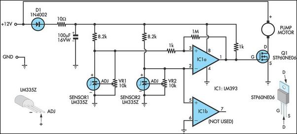
This circuit optimizes the operation of a solar hot water system. When the water in the solar collector is hotter than the storage tank, the pump runs. The circuit comprises two LM335Z temperature sensors, a comparator, and a MOSFET. Sensor 1 connects to the solar collector panel, while Sensor 2 connects to the hot water panel. Each sensor includes a trimpot to allow adjustment of the output level. In practice, VR1 and VR2 are adjusted so that both Sensor 1 and Sensor 2 have the same output voltage when they are at the same temperature. The sensor outputs are monitored using comparator IC1. When Sensor 1 produces a higher voltage than Sensor 2, indicating that Sensor 1 is at a higher temperature, pin 1 of IC1 goes high and drives the gate of MOSFET Q1, which in turn drives the pump motor. IC1 includes hysteresis to prevent oscillation when both sensors produce similar voltages. Hysteresis is implemented using a 1 MΩ feedback resistor between output pin 1 and non-inverting input pin 3, along with a 1 kΩ input resistor. This configuration provides a nominal 12 mV hysteresis, meaning that the voltage at Sensor 1 or Sensor 2 must differ by 12 mV for changes in the comparator output to occur. Since the outputs of Sensor 1 and Sensor 2 change by approximately 10 mV/°C, a degree of hysteresis is present in the comparator. Notably, IC1 is a dual comparator, with the second unit unused; its inputs are tied to ground and pin 2 of IC1, setting the pin 7 output high. The output is an open collector, resulting in a high impedance state. MOSFET Q1 is rated at 60 A and 60 V, making it suitable for driving inductive loads due to its avalanche suppression capability, which clamps any inductively induced voltages exceeding the MOSFET's voltage rating. The sensors are initially adjusted to ensure both measure the same temperature, which can be done at room temperature by adjusting the trimpots so that the voltage between ground and the positive terminal reads the same for both sensors. Optionally, the sensors can be set to a 10 mV/°C change with outputs referred to the Kelvin scale, which is 273 K at 0 °C. Therefore, at 25 °C, the sensor output should be set to (273 + 25 = 298) x 10 mV, resulting in 2.98 V. It is important to protect the sensors from moisture exposure, as incorrect outputs may result. Neutral cure silicone sealant can be used for protection. The sensors can be mounted by clamping them directly to the outside surface of the solar collector and on an uninsulated section of the storage tank. The thermostat housing is typically a suitable position on the storage tank.
The circuit operates by continuously monitoring the temperatures of the solar collector and the hot water storage tank using the LM335Z temperature sensors. The output from each sensor is adjusted through the trimpots to ensure accurate readings at the same temperature. The comparator IC1 plays a crucial role in determining when to activate the pump based on the temperature differential between the two sensors. The hysteresis feature is essential for stable operation, preventing rapid switching of the pump when temperatures are close to equal.
The MOSFET Q1 is a key component that allows for efficient control of the pump motor, capable of handling significant current and voltage levels, thus ensuring reliable operation under various load conditions. The use of an open collector output from IC1 allows for flexibility in interfacing with other components or systems, as it can be connected to different types of loads without being limited by output voltage levels.
Proper installation and calibration of the sensors are vital for maintaining the system's efficiency. The recommended mounting positions ensure that the sensors accurately reflect the temperatures of both the collector and the storage tank, while the protective measures against moisture help maintain sensor integrity over time. Overall, this circuit design provides an effective solution for optimizing solar hot water systems, enhancing energy efficiency and system performance.This circuit optimises the operation of a solar hot water system. When the water in the solar collector is hotter than the storage tank, the pump runs. The circuit comprises two LM335Z temperature sensors, a comparator and Mosfet. Sensor 1 connects to the solar collector panel while Sensor 2 connects to the hot water panel. Each sensor includes a trimpot to allow adjustment of the output level. In practice, VR1 and VR2 are adjusted so that both Sensor 1 and Sensor 2 have the same output voltage when they are at the same temperature. The Sensor outputs are monitored using comparator IC1. When Sensor 1 produces a higher voltage than Sensor 2, which means that sensor 1 is at a higher temperature, pin 1 of IC1 goes high and drives the gate of Mosfet Q1.
This in turn drives the pump motor. IC1 includes hysteresis so that the output does not oscillate when both sensors are producing a similar voltage. Hysteresis comprises the 1MO feedback resistor between output pin 1 and non-inverting input pin 3 and the input 1kO resistor.
This provides a nominal 12mV hysteresis so that voltage at Sensor 1 or Sensor 2 must differ by 12mV for changes in the comparator output to occur. Since the outputs of Sensor 1 and Sensor 2 change by about 10mV/ °C, we could say that there is a degree of hysteresis in the comparator.
Note that IC1 is a dual comparator with the second unit unused. Its inputs are tied to ground and pin 2 of IC1 respectively. This sets the pin 7 output high. Since the output is an open collector, it will be at a high impedance. Mosfet Q1 is rated at 60A and 60V and is suitable for driving inductive loads due to its avalanche suppression capability. This clamps any inductively induced voltages exceeding the voltage rating of the Mosfet. The sensors are adjusted initially with both measuring the same temperature. This can be done at room temperature; adjust the trimpots so that the voltage between ground and the positive terminal reads the same for both sensors.
If you wish, the sensors can be set to 10mV/ °C change with the output referred to the Kelvin scale which is 273K at 0 °C. So at 25 °C, the sensor output should be set to (273 + 25 = 298) x 10mV or 2. 98V. The sensors will produce incorrect outputs if their leads are exposed to moisture and they should be protected with some neutral cure silicone sealant.
The sensors can be mounted by clamping them directly to the outside surface of the solar collector and on an uninsulated section of the storage tank. The thermostat housing is usually a good position on the storage tank. 🔗 External reference
