
Solid State Tesla Coil and Wireless Power
The solid-state Tesla coil (SSTC) is an innovative adaptation of Nikola Tesla's original design, incorporating modern components such as MOSFET transistors for more reliable and efficient operation. By eliminating the traditional spark gap, the circuit not only enhances safety but also allows for more precise control of the oscillation frequency. The two primary coils, configured in a counter-wound manner, create a more effective magnetic coupling with the secondary coil, leading to improved energy transfer and resonance.
The TL494 integrated circuit serves as the heart of the control mechanism, regulating the switching of the MOSFETs to maintain the desired frequency and output voltage. This adaptability is crucial for achieving resonance with the secondary coil, which is essential for maximizing the energy output of the system. The design's emphasis on using a circuit ground for high-voltage applications is a noteworthy deviation from traditional methods, suggesting that with careful design considerations, effective performance can be achieved without the need for a dedicated earth ground.
In terms of construction, the choice of solid copper wire for the primary coils ensures minimal resistive losses, while the winding technique maximizes the inductance and coupling efficiency. The use of high-quality MOSFETs, such as the STW20NK50Z in future iterations, will further enhance performance, allowing for higher switching speeds and greater power handling capabilities.
The wireless power transmission aspect of this project demonstrates the practical applications of resonant coupling, showcasing the potential for efficient energy transfer over short distances. The ability to light an incandescent bulb with minimal input power illustrates the effectiveness of the tuned system, while the emission of RF power from the receiving coil indicates the system's capability to operate in a wireless energy transmission mode.
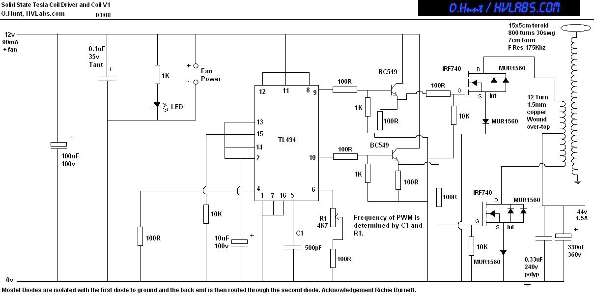
Overall, this solid-state Tesla coil project not only pays homage to Tesla's pioneering work but also pushes the boundaries of modern electronics, offering insights into the possibilities of wireless power transfer and resonant energy systems. Continued experimentation and refinement of the design will likely yield even more impressive results, contributing to the ongoing exploration of high-frequency electrical phenomena.This is a Solid State version of a Tesla coil. Eg, replacing the spark gap with Mosfet transistors and using a close coupled primary coil without capacitors. The method of driving the primary coil varies from design to design. After looking around the internet at various other peoples work, I set out to design my own. For version 1 this is just a fairly straight forward circuit, with a few protection devices. The next version will be more advanced, hopefully one which will include a self tuning system (as the output voltage drawn effects the resonant frequency proportionally). The Secondary coil or resonator comes fromthe Tesla Coil v1 project. The Self resonant frequency of this coil with topload is 174Khz. So the driver will need to produce a frequency that matches this. This is where my setup differentiates from others in that I use only 2 mosfets to drive the coil. To do this I use two primary coils. One wound clockwise up the base of the secondary and one wound counterclockwise down over the top of the first primary coil.
Both a of equal length wire and of the same guage. The center or top end of the two primarys are joined together and are connected to the poisitive 44v rail. The 2 mosfets serve as switches to ground for the two primarys, creating and AC system (The TC secondary will actually see a sinusoidal waveform due to the LC circuit).
The IC I have used for the SSTC is the well known TL494 Switch mode power supply controller. The design is very similar to my Plasma Sonic Speaker driver and incorporates some of the techniques used in that project. The circuit is pretty self explanatory. The only thing that may need clarification is the ground return from the secondary. As I am using a transformer from the mains to produce the 44V to drive the primary, I am simply using the negative side (circuit ground) of this as my HV ground.
This is contrary to normal TC`s as they state you must use a solid earth ground. I have not experienced any problems with doing it my way, but please bear this in mind if you find equipment in your house being dissrupted. Just make sure you use large and small capacitors across the circuit supply to catch any noise (even rf chokes on the power lines maybe a good idea for high power levels).
The specs for the Tesla Resonator can be seen on the Tesla Coil V1 page. The primary wire used is solid copper 13A household cable and is wound like this; Direction: CW For:12T, then: + center tap, Direction: CCW back over the top of CW For: 12T. Mosfets used in this circuit are IRF740`s (or FQA55N10), these are ok but this experimentor has found that there are far better mosfets to use than these.
The next revision will use these, STW20NK50Z. Another technology that was demonstrated by Nikola Tesla, is the Wireless transmission of power. He demonstrated this from his laboratory in Colorado Springs and achieved a transmission distance of over 25 miles. The concept is simple. You take two identical secondary coils, use 1 as the transmitter and one as the receiver. These form a "tuned system", whereby signals presented to the transmitter and sent to the receiver. The system is incredibly good and very effecient. I have personally achieved a distance of just over 1 meter, not amazing, but I am limitted at the moment by the mosfets I am using.
The RX secondary ground is connected to the 44V negative rail (this could also be the earth if you use the earth for the TX coil, in this way, the distance between them can be increased). The receiving coil has a 12 Turn primary coil around the base. The output from the primary is connected to a 240V 25W incandescent bulb. When the transmitting coil is powered up, the bulb glows to about half brightness! This is quite amazing since I am only feeding in about 60W of power. It has also been noticed that the receiving coil emits rf power as well. Fluro lights can be seen to glow around the receiving coil`s sec 🔗 External reference
Related Circuits
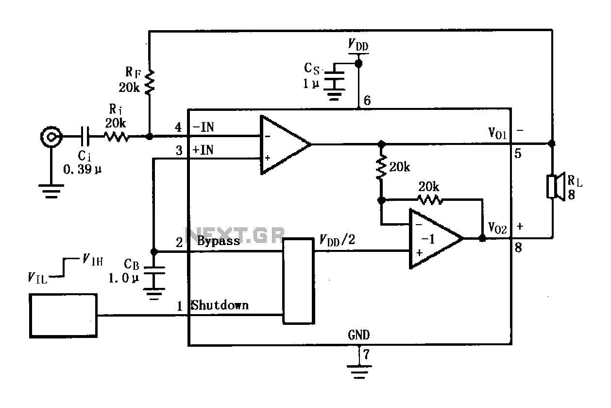
The LM4819 audio power amplifier is designed to amplify audio signals. An audio signal is input through the coupling capacitor (Ci) and the resistor (Ri) applied to the inverting input terminal (pin 3) of the amplifier. The inverting input...
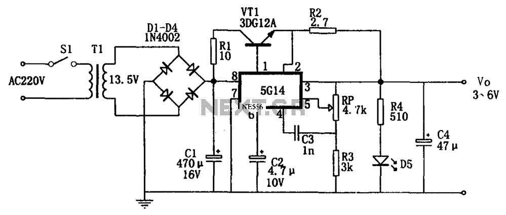
As shown in the figures, this is a practical adjustable power supply. It utilizes an integrated voltage regulator (5G14) in conjunction with a 3DG12A transistor for current spreading, providing an output voltage range of 3 to 6V. The rated...
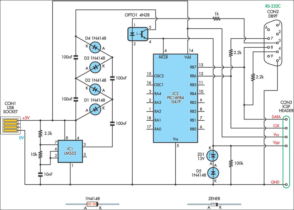
This simple circuit can be used to program the PIC16F84 and similar flash memory type components. It utilizes a 555 timer integrated circuit (IC) to generate the programming voltage from a +5V power supply, enabling operation from a computer's...
The circuit was designed to increase an input signal of 4 Watts to 6 Watts, operating within the VHF radio frequency band, specifically for FM transmission. This circuit is engineered to amplify radio frequency signals in the VHF band, which...
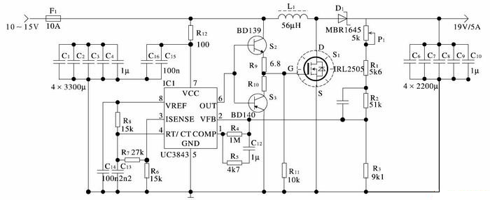
The car cigarette lighter outputs a DC voltage of 12 V, which does not exceed 13.8 V even when the engine is running. A voltage of 19 V is lower than the normally required levels. The car cigarette lighter circuit...
If a tool is needed to save electricity, a simple power-saving device circuit diagram is suitable for testing. This tool can save electricity in a home by 10-25%. Its operation involves reducing the cosine component of AC current curves,...