
VHF Amplifier with 30 Watts Power
This circuit is engineered to amplify radio frequency signals in the VHF band, which typically ranges from 30 MHz to 300 MHz. The primary function of the circuit is to enhance the power output of an input signal from 4 Watts to a higher level of 6 Watts. This amplification is crucial for ensuring that the transmitted signal can cover a larger area and maintain clarity and strength, which is particularly important in FM broadcasting.
The circuit design likely incorporates a combination of RF transistors or amplifiers that are optimized for VHF frequencies. These components are selected for their ability to handle the specific frequency range and power levels required. The circuit may also include impedance matching networks to ensure maximum power transfer from the input source to the amplifying stage, minimizing signal loss.
Power supply considerations are essential in this design, as the circuit must be able to provide adequate voltage and current to support the amplification process without introducing noise or distortion. Bypass capacitors may be used to filter out any unwanted high-frequency noise, ensuring that the output signal remains clean and stable.
Thermal management is another critical aspect of the circuit design. As the power output increases, so does the heat generated by the amplifying components. Adequate heat sinking or cooling methods must be implemented to prevent thermal runaway and ensure reliable operation over prolonged periods.
Overall, this circuit is a vital component in VHF FM transmission systems, enhancing signal strength and quality for effective communication and broadcasting applications.The circuit was designed for the purpose of increasing an input signal of 4 Watts to 6 Watts operating on the VHF radio frequency band specifically the FM.. 🔗 External reference
Related Circuits
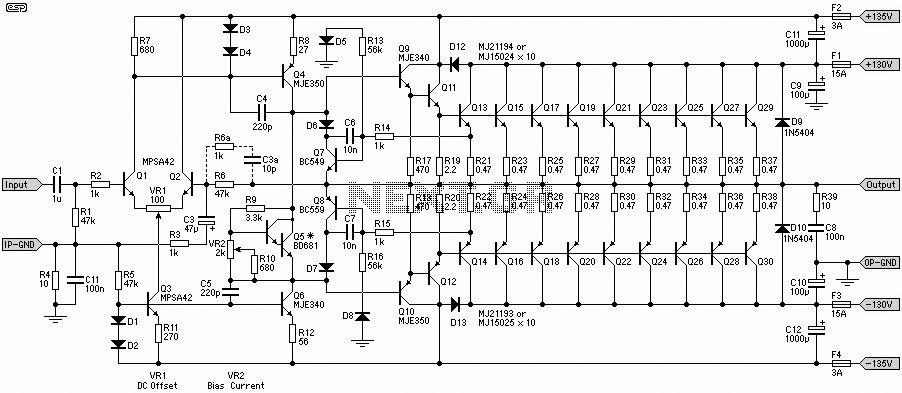
A 1500W power amplifier circuit design diagram created by Rod Elliott. The circuit utilizes 10 pairs of power transistors, specifically MJ15024 and MJ15025, or alternatively MJ21193 and MJ21194. The 1500W power amplifier circuit is designed for high-performance audio applications, providing...

The NJM2670 is a general-purpose 60V dual H-bridge drive integrated circuit (IC). It features a pair of H-bridges, a thermal shutdown circuit, and an alarm output. The alarm output is capable of detecting application issues, thereby significantly enhancing system...
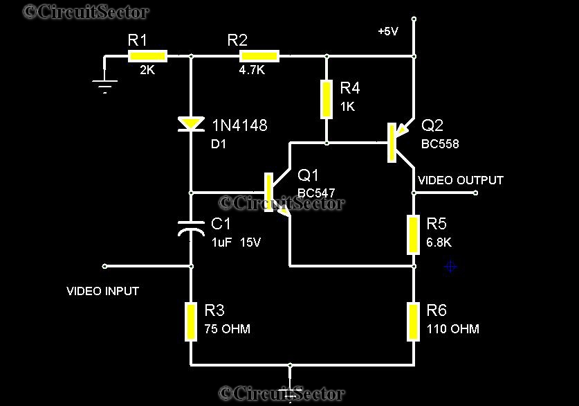
There are instances when it is necessary to view video clips captured by a digital camera on a television. This can be accomplished by connecting the camera's video output to the television's video input. However, a direct connection is...
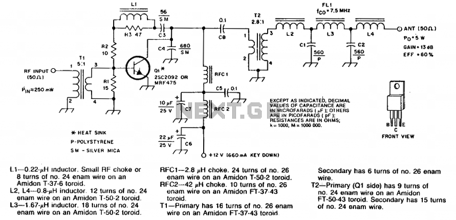
Numbered components are designated for PC-board layout purposes. C5 and C8 are disc ceramic capacitors. C6 and C7 are tantalum or electrolytic capacitors. R1, R2, and R3 are 1/4 W carbon composition resistors. Silver-mica capacitors may be substituted for...
Using the versatile L200 voltage regulator, this power supply has independent voltage and current limits. The mains transformer has a 12volt, 2 amp rated secondary, the primary winding should equal the electricity supply in your country, which is 240V...
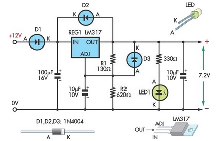
This circuit allows an external 12V sealed lead-acid (SLA) battery to power a camcorder that typically operates with an internal 7.2V battery. Obtaining such batteries for older camcorder models can be challenging and costly. The circuit functions as a...