
Simple Power Saving Devices
The described power-saving device operates on the principle of power factor correction, which enhances the efficiency of electrical systems by reducing the phase difference between voltage and current in AC circuits. The circuit typically includes a coil that acts as a current sensor, measuring the AC load. This coil is often wound around a core material that enhances its inductive properties, ensuring accurate current readings.
The capacitor in the circuit plays a crucial role in storing and releasing electrical energy, thus smoothing out the current waveform and reducing harmonics. The choice of capacitor is essential, as higher-quality capacitors can handle greater voltage and current without failure, ensuring reliability and longevity in the circuit's operation. The switch (SW) serves as a safety mechanism, allowing for easy disconnection of the circuit during maintenance or in case of an anomaly, preventing potential damage to the components.
For effective implementation, the circuit should be designed with careful consideration of the ratings of all components, ensuring they are suitable for the expected load. Proper insulation and housing in a plastic box are necessary not only for safety but also to protect the components from environmental factors. This setup can be particularly beneficial in residential applications, where electricity consumption can be significantly reduced, leading to lower energy bills and a reduced carbon footprint.If you need a tool to save electricity you use, so in this article a simple power saving device circuit diagram is very suitable for you to test. Basically, this tool can really save electricity in your home from 10-25%. Work of this tool is simply to reduce the number of cosines of the AC current curves which will be read on a gauge to measure a
mile in your home. The power saving device will work if there is an AC load through a coil of wire sensors to measure the amount of AC current through it. Or a scientific theory is how we can reduce the possibility of the largest peak (peak of the curve of AC (sine-cosine) to read so low.
power saving device component which affects the flow of AC and condenser or capacitor or inductor loop. You can do is flow air conditioner filters before entering the electricity network in your home. Here is a schematic power saving device drawing: Create the circuit in a plastic box. then use a capacitor with good quality, the more expensive the better. to SW is functioning as a safety in case of short circuiting due to the capacitor. 🔗 External reference
Related Circuits
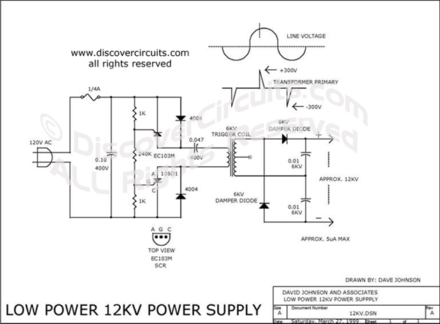
For generating approximately 12,000 volts DC for an ion generator, this circuit design may be suitable. It draws power from a 120 VAC power line and utilizes a small 6 kV camera flash trigger coil. The output signal is...
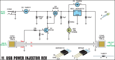
A portable USB hard drive is an effective means to back up data; however, issues may arise if the USB ports do not provide sufficient power to operate the drive. A modified version of the Silicon Chip USB Power...
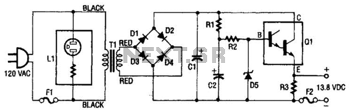
This regulated power supply consists of a step-down transformer T1, a full-wave rectifier bridge (D1 through D4), and a filtering regulator circuit made up of C1, C2, R1, R2, R8, D5, and Q1. When 120 Vac is provided, the...
This surround-sound decoder is based on the "Hafler" principle, first discovered by David Hafler sometime in the early 1970s. The original idea was to connect a pair of speakers as shown in Figure 1, for use as the rear...
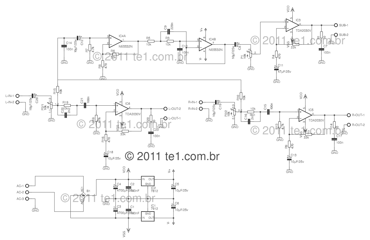
This circuit is a complete application for a 2.1 amplifier system, consisting of two satellite speakers powered by a TDA2030 and one subwoofer. This 2.1 system is commonly utilized in commercial applications as an amplifier for computers, enhancing audio...
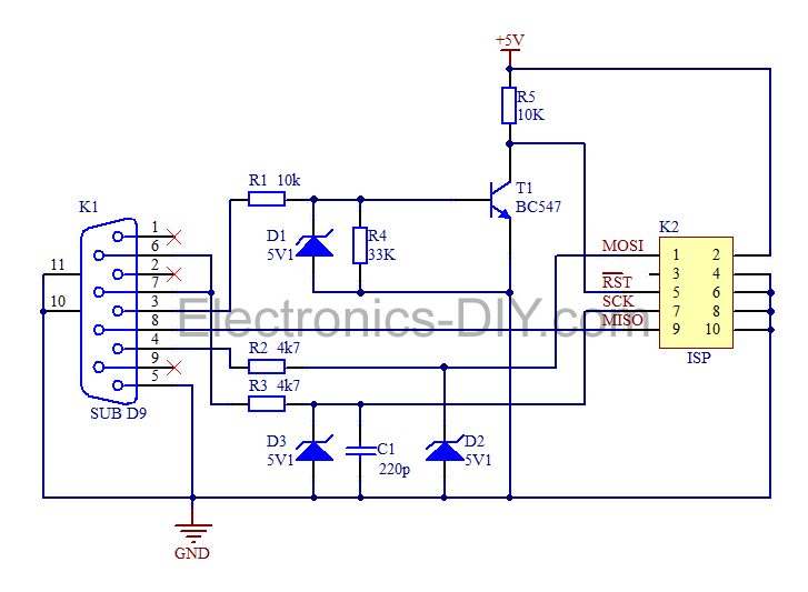
This is a simple AVR programmer designed for Atmel microcontrollers from the AVR family that support serial programming. The programmer connects to a PC via the RS232 serial interface and is compatible with PonyProg or Avrdude software. It is...