
Solving the USB Only Chicken or Egg Problem

The schematic for this setup typically involves a USB hub with its ports configured to operate in a disabled state, allowing for the manipulation of the data lines for programming purposes. The FTDI chip interfaces with the USB hub, providing a bridge for communication with the AVR microcontroller. The design incorporates resistors, particularly the 4.7K resistor, which is crucial for pull-up functionality, ensuring reliable data transmission. The connections between the USB ports and the microcontroller must be meticulously arranged to prevent signal interference and ensure that the programming signals are accurately transmitted. The use of logic gates in this design allows for the generation of the necessary control signals required for programming the microcontroller, thereby overcoming the limitations typically imposed by the lack of a pre-programmed chip. This innovative approach showcases the versatility of USB technology in microcontroller programming applications, enabling enthusiasts and engineers alike to explore the capabilities of AVR microcontrollers without the need for traditional programming hardware.Many excellent ISP (In System Programming) designs exist for 8 bit AVR microcontrollers. However, most require a pre-programmed microcontroller, or the "Chicken or Egg" problem: you can`t program microcontrollers unless you have one already programmed. Parallel Port or Serial Port solutions have existed, but many modern computers no longer have these ports.
The FTDI USB-to-serail chip can be used as well. Until now it`s been widely thought impossible to solve the Chicken or Egg problem using only USB, without preprogrammed or specialized USB chips. USB defines a device reset state, where a hub shorts both data lines to ground for 10 milliseconds. USB hubs also implement a disable feature, where no data is routed to the disabled port, and both data lines are kept at high impedance.
Devices contain a pullup resistor, which is used by the hub to detect device arrival, at a disabled port. Normally these features are managed automatically by your operating system. But by taking control of a hub and keeping its ports disabled, each port can be used as a single bit input, and/or a momentary active-low "open collector" pulsable output.
Two pulsable outputs can drive a set-reset latch to create a single steady-state output. These I/O capabilities are sufficient for AVR ISP programming! If you are just getting started with AVR microcontrollers, ISP programming is not a good place to begin, even if you buy a ready made programmer, and certainly not by trying to build your own! Ready-to-use boards like Teensy (yes, a shameless plug, as I make this one) or Arduino just plug into any USB port and are ready to go, with easy to use software tools.
Troubleshooting electronics and software can be taxing even for experienced engineers, so it`s highly recommended to start with a foundation that`s as trouble-free as possible. HUB ISP is, well. not. HUB ISP is certainly not a viable replacement for regular "chicken or egg" AVR ISP programmers, which are much faster and more reliable, and maybe even cheaper.
eg, Teensy running the ArduinoISP code (yup, another shameless plug). However, if you love to tinker or you`re just curious how this could possibly work with only USB and no programmable chip, without even any parts designed for USB, only logic gates and resistors, then read on! You must edit config. h and include those ID numbers. Then just compile with "make". If you get an error about "usb. h" missing, you probably need to install a "devel" libusb library package. Probably the simplest but most tedious step is cutting and preparing the USB cables. On these 4, the plastic jacket was really tough, and the wires inside really delicate. All four cables need the green wire, and at least one red and one black are needed (they`re from the same power inside the hub).
It`s a good idea to cut the extra white, red and black lines at slightly different lengths, and not close to the frayed metal shield, so they don`t accidentally short to each other. If you have a soldering iron, tinning the ends of the wires will make them much nicer for sticking into the breadboard holes.
Otherwise, just twist them tightly and watch for stray bits of wire later on. Opps, I drew ports 1 and 2 with red wires and ports 3 and 4 with black wires on this schematic, but I actually used the cables with black wires on ports 1 and 2, and the cables with red wires on ports 3 and 4. It doesn`t really matter, as all 4 red wires connect to the same +5 volt power inside the hub and all grounds are connected together.
Even just 1 red wire and 1 black wire from any of the 4 cables is enough. Of course, it DOES matter that each green wire goes to the correct place. The test program will help you make sure it`s all hooked up properly before risking a real AVR chip. Here is a closeup photo of the circuitry. There is a 4. 7K resistor, the one attached between pin 11 and port 4`s green wire, hiding behind one of the USB cables! 🔗 External reference
Related Circuits
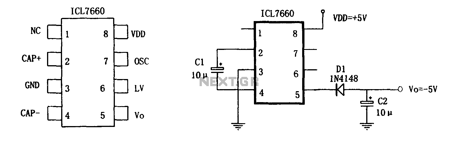
The circuit consists of two capacitors arranged as indicated by the ICL7660, which is utilized for external power conversion. The power supply employs the dedicated integrated circuit ICL7660 for polarity inversion and external charge pump capacitors, forming a DC/DC...

This document serves as a resource for developers who are new to Texas Instruments (TI) ARM-based processors, as well as for seasoned developers seeking to deepen their understanding of the different ARM architectures. It starts with an overview of...
This kit is based on an original design by Jan G0BBL and serves as a versatile replacement for the older "Rocky" serial interface kit. It includes control of the programmable oscillator on the V6, 3 RXTX (and the older,...

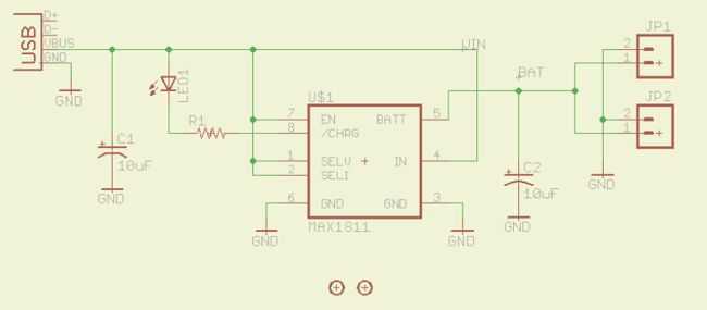
The popular USB interface can charge a portable device while transferring data. But for high-capacity batteries, the 500-mA output current of USB hosts and powered hubs greatly extends the charging time. Thus, a system that accepts charging power from...

This article is the result of positive feedback on previous hardware articles. Readers of LinuxFocus expressed interest in interfacing with the USB bus. This solution utilizes the LCD display from a May 2002 article and connects it to the...
Lithium Polymer Batteries are a very common source of power today. Many electronics gadgets have one inside, and they have some reasonable features. I've bought great batteries, with different sizes and capacities for my electronics projects. So long I'm...