
USB I2C Interface
This electronic kit offers a robust solution for enthusiasts looking to upgrade their serial interface capabilities while providing a comprehensive guide for assembly and testing. The integration of I2C protocol facilitates efficient communication between components, enhancing the overall functionality of the system. The step-by-step assembly instructions are designed to cater to a range of skill levels, ensuring that both novice and experienced builders can successfully complete the project. The emphasis on thorough testing and documentation fosters a systematic approach to troubleshooting, which is essential in the realm of electronics where precision is paramount. The inclusion of advanced soldering techniques and methods such as the reflow process demonstrates a commitment to modern assembly practices, catering to a diverse audience of builders. Overall, this kit not only serves as a practical tool for interfacing but also as an educational resource, empowering builders with the knowledge and skills necessary for successful electronic assembly.This kit is based upon an original design by Jan G0BBL and provides a multi-faceted replacement for the older "Rocky" serial interface kit. The kit includes: The control of the programmable Oscillator on the V6. 3 RXTX (and the older, now retired Lite + Xtrall V8. 3 RX) kits, over a USB cable, using the I2C protocol of two serial streams (the clocki ng stream, named "SCL", and the data stream, named "SDA"). With the proper software drivers, this kit removes the 16 frequency constraint of the RX V8. 3 and RXTX V6. 3 kits For more information on the firmware and its capabilities/configuration, refer to Bob G8VOI`s Users Manual and Fred PE0FKO`s configuration manual. You should access and download relevant portions of these guides to assist you with the setup in the final phase of this build.
The builder should read each page completely, taking care to compare the "bare board" photos with the completed stage photos, before undertaking actual construction. For the non-expert builders among us, this site takes you through a stage-by-stage build of the kit. Each stage is self-contained and outlines the steps to build and test the stage. This ensures that you will have a much better chance of success once you reach the last step, since you will have successfully built and tested each preceding stage before moving on to the next stage.
If you are not experienced at soldering (and even if you are somewhat experienced at soldering), refer to Tom N0SS`s excellent tutorial on basic soldering techniques. For the more adventurous, there is a process using solder paste and an electric oven called the reflow process, which can be used to install all the SMT chips to one side of the PC Board.
This is documented by Guenael Jouchet in the following Youtube segment: You will need a well-lit work area and a minimum of 3X magnification (the author uses a cheap magnifying fluorescent light with a 3X lens. This is supplemented by a hand-held 10 X loupe - with light - for close-in inspection of solder joints and SMT installation.
You should use a cookie sheet or baking pan (with four sides raised approximately a half an inch) for your actual work space. It is highly recommended for building on top of in order to catch stray parts, especially the tiny SMT chips which, once they are launched by an errant tweezer squeeze, are nigh on impossible to find if they are not caught on the cookie sheet.
It is most important to solidly clamp the PCB in a holder when soldering. A "third-hand" (e. g. , Panavise or the Hendricks kits PCB Vise ) can hold your board while soldering. In a pinch, you can get by with a simple third-hand, alligator clip vise. Jan G0BBL suggests "A very cheap way is to screw a Large Document Clip to a woodblock which will clamp the side of a PCB. " Each stage will have a "Testing" Section, outlining one or more tests that, when successfully completed, provide you with the confidence and assurance that you are heading in the right direction towards a fully tested and built transceiver.
When you perform a test, you should always record the results of the test where indicated in the Testing section. This will make troubleshooting via the reflector much easier, since you will be communicating with the experts using a standard testing and measurement regime.
When comparing measurements to those published in these notes, the builder should be aware that actual and expected values could vary by as much as +/- 10%. The idea behind furnishing "expected/nominal" measurement values is to provide the builder with a good, "ballpark" number to determine whether or not the test has been successful.
If the builder has concerns about his measurements, he should by all means pose those concerns as a query in the Softrock reflector so the experts can provide assistance. It goes without saying that you should ALWAYS precede any tests with a very careful, minute inspection (using the best light and
🔗 External reference
Related Circuits
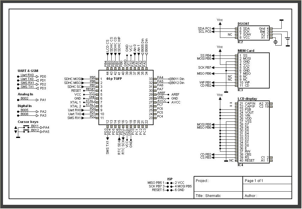
AVRtools features an intuitive graphical user interface and utilizes predefined function blocks. It provides a wide array of basic functions, including timers, counters, logic operations, and analog signal processing. Additionally, it includes function blocks for sending SMS messages over...
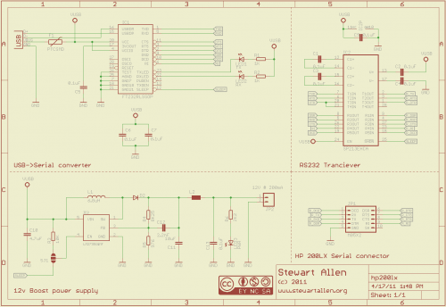
A personal digital assistant was introduced in 1994, often referred to as a palmtop computer. It was notable for being, with minor exceptions, an MS-DOS-compatible computer in a palmtop format. It featured a monochrome graphic display, a QWERTY keyboard,...
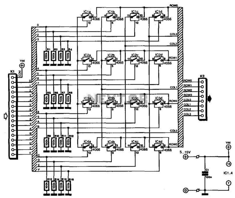
Keyboards can be classified into two categories based on the connection method of the switches: those with a common connection and those arranged in a matrix. The matrix type offers the significant advantage of minimizing the number of connections,...
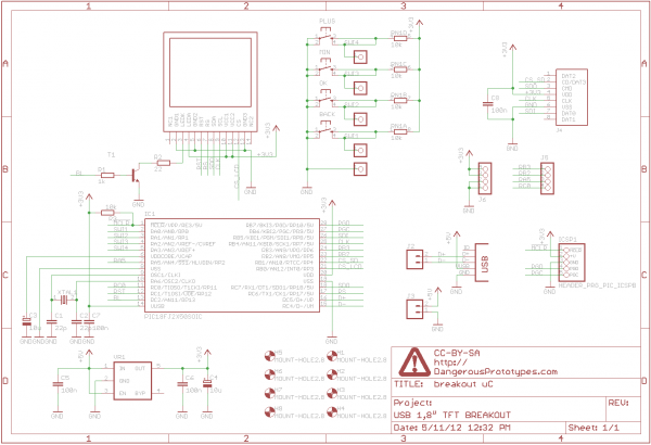
A 1.8" TFT display was sourced from China, and a breakout board was designed for it. This version not only breaks out the pins but also includes a USB-enabled microcontroller and several buttons for graphical user interface (GUI) projects....
The audio ground is completely isolated from the digital ground. The top copper layer is utilized as a shield for both the audio and digital ground, which aids in preventing the audio section from picking up noise from the...
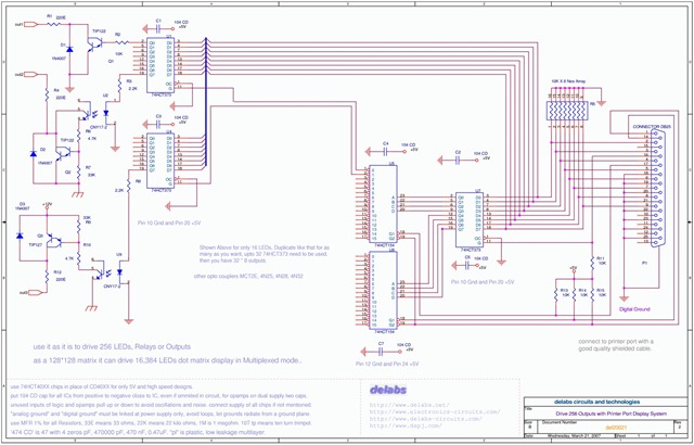
The following schematic illustrates the design of a Parallel Port Interface Circuit Diagram utilizing the 74HCT373. The 74HC/HCT373 are high-speed silicon-gate CMOS devices that are pin-compatible with low-power Schottky TTL (LSTTL). This parallel port interface circuit can drive 256...