
lf286 Linux USB LCD display with watchdog and buttons
The integration of the FT232BM chip into the circuit design allows for effective communication between the microcontroller and the USB interface. The FT232BM serves as a bridge, enabling serial communication over USB, which simplifies the design process by eliminating the need for a separate RS232 interface. The chip's functionality is enhanced by the availability of drivers that support various operating systems, ensuring broad compatibility and ease of use.
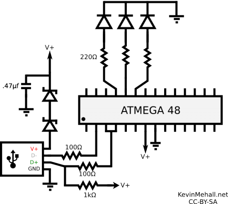
The circuit schematic should include the necessary connections: the USB connector connects to the FT232BM chip, which in turn connects to the microcontroller's Rx/Tx pins. A 6 MHz crystal oscillator is required for timing purposes, ensuring that the FT232BM operates correctly. Additionally, the inclusion of a ferrite bead in the circuit aids in filtering out high-frequency noise that may interfere with the USB communication, maintaining signal integrity.
Power management is a critical aspect of this design. The requirement for the device to consume less than 100 mA while powered via USB necessitates careful selection of components and design considerations to minimize power draw. The microcontroller's ability to enter low-power modes is essential for compliance with USB suspend mode, allowing the device to remain operational while conserving energy. The decision to utilize "idle mode" could lead to higher power consumption than specified, but it may still function adequately without triggering detection by the USB host controller.
Overall, this circuit design presents a straightforward solution for interfacing a microcontroller with the USB bus, leveraging the capabilities of the FT232BM chip while addressing power consumption challenges and ensuring compatibility across different operating systems.This article is the result of the very positive feedback on the hardware articles that I have written so far. You LinuxFocus readers are really a great audience! Some of you wanted to know how to interface the USB bus. So here is a nice solution. We use the LCD display from the May 2002 article and make it work with the USB bus. The whole thing wi ll be powered from the USB bus. Therefore you do not need any extra power supply. For this article you need at least a partial installation of the Linux AVR development environment. How to set it up is described in this article: Programming the AVR Microcontroller with GCC. USB is cool because it is a modern interface and it offers the possibility to power the devices directly via the USB bus. The connectors are small and high volumes of data can be transported over a small cable. That`s the positive things about USB. The down side is that hardware design is difficult due the high frequencies and the protocol is rather complex.
Just take a look a the specifications (, you want the 1. 1 specification) and you will be shocked. It`s 327 pages long and very difficult to understand. No wonder that there are soooo many faulty implementations of USB devices. A more user friendly introduction can be found at but the specification is still complex. What to do How can we interface our Microcontroller to the USB bus FTDI, a Scottish company, has the solution ( ). They offer a chip which implements a USB serial interface. One side of the FT232BM chip is rs232 and the other USB. In other words you just replace the MAX232 which you previously needed for the power conversion on the rs232 lines with this FT232BM chip and you are done.
The FT232BM is a true cross platform solution. Drivers are available for multiple operating systems. The Linux kernel module is called ftdi_sio and is open source. It is part of the standard Linux kernel. The FT232BM offers more than just a USB to rs232 conversion and the Linux kernel module is still under development to implement all functions. The USB to rs232 is however ready and I was e. g able to use a standard Redhat 7. 3 Kernel (2. 4. 18) without recompilation or any modification. Just plug it in. With my Redhat 7. 3 all modules would load automatically when I plug in the USB connector. If it does not work for your Linux distribution then check that you have the following modules (for USB-UHCI): The circuit is straight forward.
You just insert the FT232BM between the Rx/Tx lines of the Microcontroller and the USB connector. A 6 Mhz Crystal and some other parts are needed which are described in the design specification from FTDI. The ferrite bead (in the schematic on the right) is a little coil which filters high frequencies (the USB bus runs at 48Mhz).
You can also wind 10 loops of a thin wire over a 1K resistor and use it as a coil. One thing to pay attention to is the power consumption. You must consume less than 100mA if you design a bus powered device. In addition your device must support USB suspend mode. When the pin named "sleep" on the FT232BM goes low then the device must consume less than 0. 5mA. The latter is a very tough requirement to implement. The AVR supports an "idle mode" where it consumes less than 2mA and a "power down" mode where it consumes only 20uA. It seems however easier to wake up the Microcontroller from "idle mode". I have therefore decided to use "idle mode" even if this violates the USB specification a little bit.
The optional background light of the display will be switched off and the whole circuit will then consume 3mA. 3mA is more than 0. 5mA but the USB host controller chips can not measure the current so accurate that they will detect this.
It should work. Having said all this I must admit that I don`t have a computer which supports suspend. Therefore I could not test this part. If you have a computer, probably a modern Laptop, that supports suspend then please te 🔗 External reference
Related Circuits
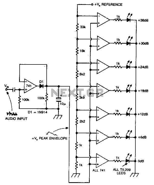
A vertical column of LEDs is configured so that as the audio signal level rises, an increasing number of LEDs illuminate. The LEDs are arranged in increments of 6 dB. The circuit features a fast response time and a...
For several recent projects, a request was made to provide engaging and informative display units. A versatile unit was developed that can be utilized across different applications. It was designed for aesthetic appeal, capable of displaying both graphics and...
The article on the RGB LED fader has been one of the most visited articles on this blog. Since its publication, another microcontroller-based RGB LED project has been designed and built, this time controlling the colors from a computer...
The LCD in question has more pins than the microcontroller. It was not possible to expand the image for a better view. Unless there is a strong preference for using this display, it is recommended to obtain a Hitachi-compliant...
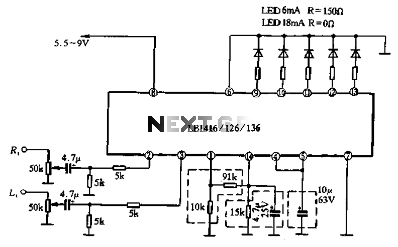
A common single five lamp drive circuit is the LB1416/26/36, which is packaged in a double row of finned-line 14 pins. The circuit contains two input amplifiers and five voltage comparators, allowing it to drive both AC and DC...
An HD44780 Character LCD is a liquid crystal display (LCD) device designed for interfacing with embedded systems. These screens are available in various configurations, including 8x1 (one row of eight characters), 16x2, and 20x4. The most commonly produced configuration...
Warning: include(partials/cookie-banner.php): Failed to open stream: Permission denied in /var/www/html/nextgr/view-circuit.php on line 713
Warning: include(): Failed opening 'partials/cookie-banner.php' for inclusion (include_path='.:/usr/share/php') in /var/www/html/nextgr/view-circuit.php on line 713