
Some thoughts on DC/DC converters
In many electronic applications, it is essential to convert a primary source of direct current (DC) power into various voltage levels suitable for different components within a system. This conversion is particularly relevant in battery-operated devices where the nominal voltage of the battery may not match the voltage requirements of the electronic circuitry.
To achieve this, DC-DC converters are employed. These converters can step up (boost) or step down (buck) the voltage levels, ensuring that all parts of the circuit receive the appropriate voltage. A common configuration for such converters includes the use of inductors, capacitors, and switching elements such as transistors or MOSFETs.
For instance, a buck converter reduces the input voltage by switching the transistor on and off, controlling the energy transferred to the inductor. When the switch is closed, current flows through the inductor, storing energy in the magnetic field. When the switch opens, the inductor releases energy to the output capacitor and load, resulting in a lower average output voltage.
Conversely, a boost converter increases the voltage by using a similar switching mechanism but incorporates an inductor that stores energy when the switch is closed and releases it at a higher voltage when the switch is opened.
The efficiency of these converters is a critical design parameter, often exceeding 90% in well-designed circuits. Factors influencing efficiency include switching frequency, component selection, and layout considerations.
In summary, the conversion of battery voltage to required levels in electronic circuits is a fundamental task that enables the operation of various devices, enhancing their functionality and performance through the use of DC-DC converters.Many systems require that the primary source of DC power be converted to other voltages. Battery driven circuitry is an obvious candidate.. 🔗 External reference
Related Circuits
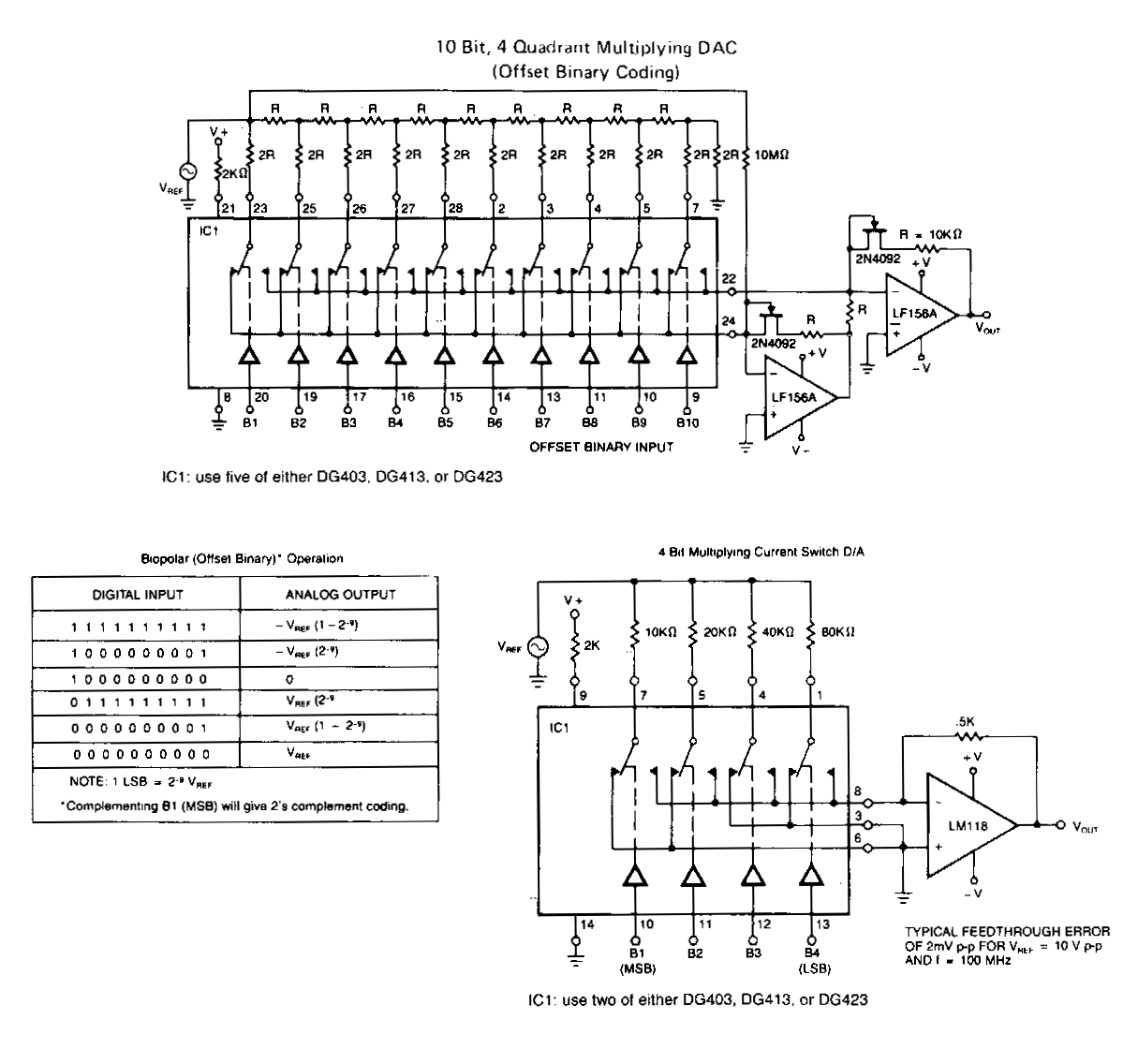
The following application circuits are designed to demonstrate several key concepts: A 2 kΩ resistor should be placed in series with the voltage source to limit supply current and mitigate negative ringing on the bit inputs. Temperature compensation for...
The lack of compensation facilitates the processes of development and testing. The figure of 6 billion frequently appears as the estimated number of cell phones in use globally. Published estimates indicate an average. The discussion of compensation in electronic circuits...
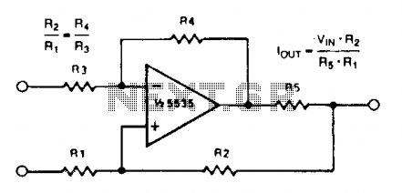
A simple voltage-to-current converter is illustrated. The output current is given by 0t or Vjn/R. For negative currents, a PNP transistor can be employed, and for improved accuracy, a Darlington pair can replace the transistor. With meticulous design, this...
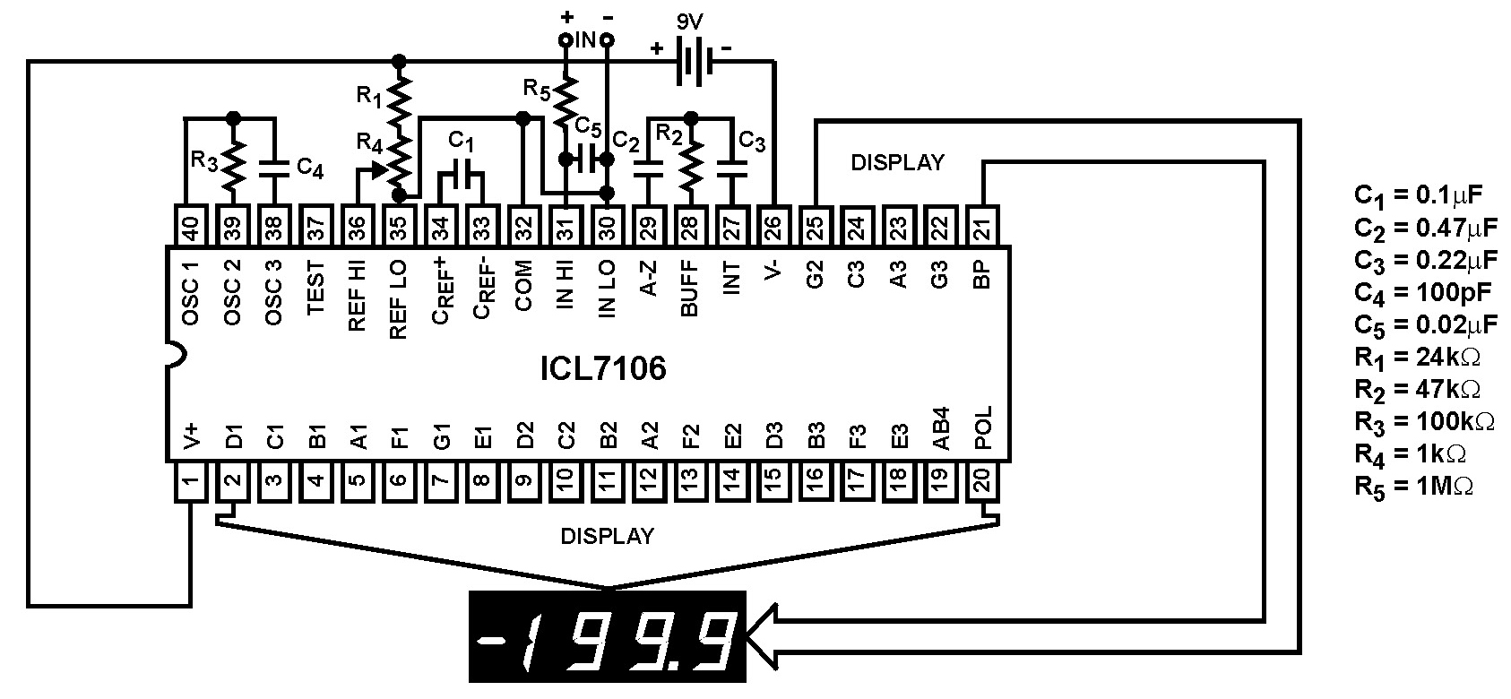
The Intersil ICL7106 and ICL7107 are high-performance, low-power, 3½ digit analog-to-digital (A/D) converters. They include seven-segment decoders, display drivers, a reference, and a clock. The ICL7106 is designed to interface with a liquid crystal display (LCD) and features a...
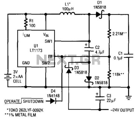
This circuit utilizes a Linear Technology LT1073 to function as a -24 V converter. The power supply can consist of two AA cells (3 V) or a 5 V source. The circuit is capable of delivering a current of...
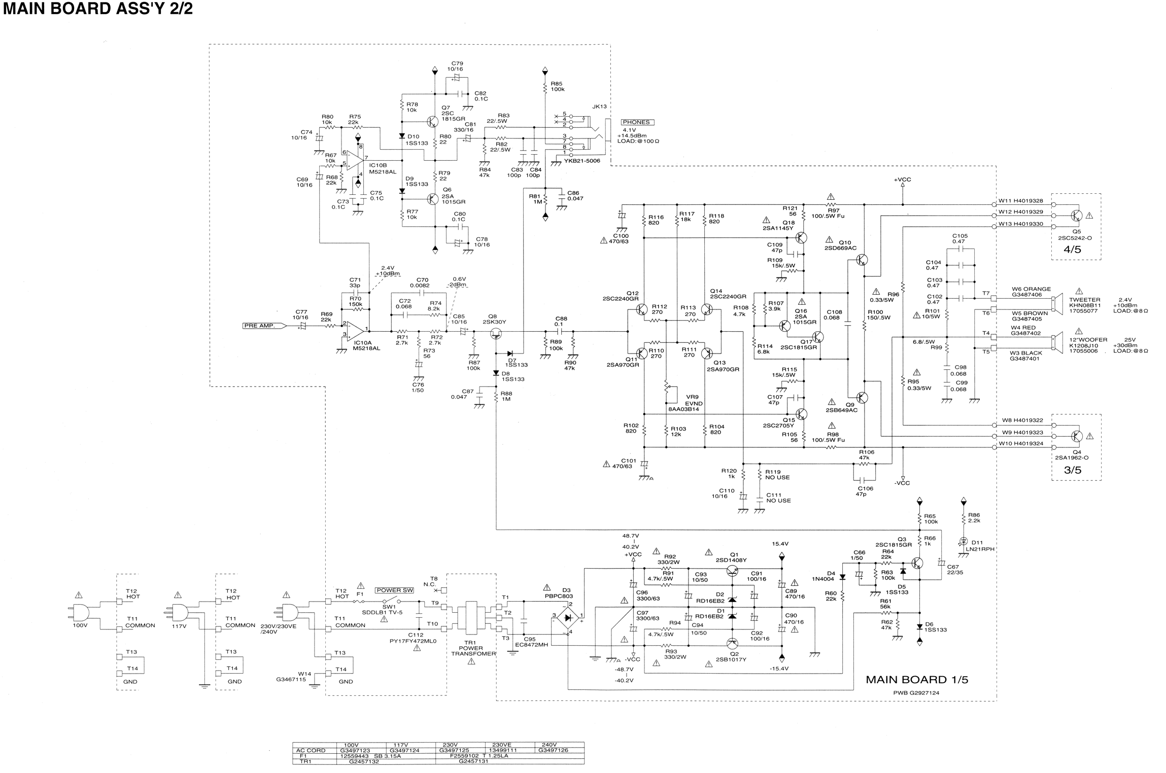
Some resistors on the circuit board of a Roland KC-300 amplifier have burned out and are so charred that their specifications cannot be determined. The resistors in question are R82, R83, R85, R92, and R93. Resistors R92 and R93...