
Voltage-to-current converters
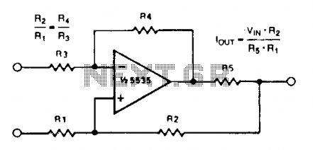
The voltage-to-current converter circuit operates by converting an input voltage signal into a proportional output current. The fundamental relationship governing the output current (I_out) is defined by the equation I_out = V_in / R, where V_in is the input voltage and R is the resistance connected in the feedback loop.
To achieve negative output currents, a PNP transistor can be utilized. This configuration allows for the inversion of the current flow, making it suitable for applications requiring negative current outputs. For applications demanding higher precision and improved linearity, substituting the single PNP transistor with a Darlington pair is advisable. The Darlington configuration consists of two transistors that provide a high current gain, thereby enhancing the performance of the converter.
The design of the circuit must consider factors such as power supply voltage, load characteristics, and thermal management to ensure reliable operation, especially when controlling currents in the range of several amps. Adequate heat sinking may be required to dissipate excess heat generated by the transistors under load conditions.
Unity gain compensation is a critical aspect of the circuit design, ensuring stability across a wide frequency range. This compensation technique involves adding a capacitor in the feedback loop, which helps to mitigate potential oscillations and ensures that the converter maintains a stable output under varying load conditions.
Overall, this voltage-to-current converter design offers versatility and precision for various applications, including signal conditioning, actuator control, and driving loads that require specific current levels.A simple voltage-to-current converter is shown in the figure. The current out is 0t or Vjn/R. For negative currents, a pnp can be used and, for better accuracy, a Darlington pah-can be substituted for the transistor. With careful design, this circuit can be used to control currents of many amps. Unity gain compensation is necessary. 🔗 External reference
Related Circuits
Optimize the layout of the MAX16974/MAX16975/MAX16976 high-performance DC-DC converters, which are standard buck controllers designed for automotive applications. The MAX16974, MAX16975, and MAX16976 are advanced DC-DC buck converters specifically tailored for automotive environments. These devices are engineered to deliver high...
Cost, size, resistance, and current capability drive the choice of inductor for most step-down DC-DC switching converters. Inductors play a crucial role in the operation of step-down DC-DC switching converters, influencing performance parameters such as efficiency, output voltage stability, and...
Many systems require that the primary source of DC power be converted to other voltages. Battery-driven circuitry is an obvious candidate. In many electronic applications, it is essential to convert a primary source of direct current (DC) power into various...
The LT3465/LT3465A are step-up DC/DC converters designed to drive up to six LEDs in series from a Li-Ion cell. Series connection of the LEDs provides identical LED currents and eliminates the need for ballast resistors. These devices integrate the...
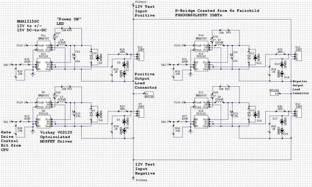
The Murata NMC1215SC DC/DC converters in a CPU-controlled H-Bridge design are experiencing repeated failures, with no obvious signs of the cause. The Murata NMC1215SC is a step-down DC-DC converter renowned for its efficiency and compact design, making it suitable for...
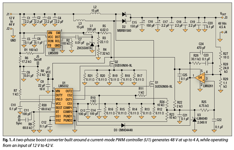
The multiphase approach has long been utilized to enhance efficiency, minimize ripple, and reduce the size of capacitors and inductors in buck converters. This method can also offer similar advantages for boost converters. The multiphase technique involves the use of...