
Sound AC switch
The described circuit effectively combines sound detection with voltage amplification to control power delivery through the use of semiconductor devices. The 741 op-amp operates as an inverting amplifier, where the input signal from the speaker is inverted and amplified based on the gain set by the feedback resistor R3. The use of a 1-megohm potentiometer for R3 allows for fine-tuning of the amplifier's gain, making it adaptable to various sound levels and environments.
The operational amplifier's output is connected to the gate of SCR1, which serves as a switch that can be turned on by the amplified signal. The SCR is a controlled rectifier that can conduct current in one direction when triggered, and it remains in the conducting state until the current flowing through it drops below a certain threshold. This characteristic makes it suitable for applications where the circuit needs to maintain its state until a manual reset is performed.
The Triac, TR1, is used to control the load, providing the necessary voltage once SCR1 is activated. The Triac can handle alternating current loads, making it ideal for applications requiring control over AC devices. The combination of SCR1 and TR1 ensures that once the sound is detected and the circuit is activated, the load remains powered until the switch is reset, allowing for a reliable sound-activated control mechanism.
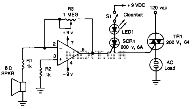
Overall, this circuit design demonstrates a practical application of operational amplifiers, SCRs, and Triacs in creating a sound-activated system capable of controlling electrical loads based on acoustic signals. The careful selection of components and their configuration plays a critical role in determining the performance and sensitivity of the sound detection and amplification system.The circuit uses a 741 op amp operating as an inverting amplifier to amplify the voltage produced by an 8-ohm speaker used to detect any sounds. The feedback resistor R3, a 1-megohm potentiometer used to vary the gain of the amplifier determines the sensitivity of the circuit.
When Si is closed in the (SET)-position and a sound is applied to the speaker, SCR1 is turned on. It will remain in conduction until the anode voltage is removed by opening SI, putting it in its RESET position. (Once an SCR is turned on, the gate or trigger has no control over the circuit.) As long as the SCR conducts, the Triac, TR1, will remain on and supply voltage to the load.
🔗 External reference
Related Circuits
The transmitter section of the circuit is built around IC1 (NE 555), which is configured as an astable multivibrator operating at 40 kHz. The output from IC1 is amplified by a complementary pair of transistors (Q1 and Q2) and...
An infra-red or wireless remote control has the disadvantage that the small, handy, remote transmitter is often misplaced. The sound operated switch has the advantage that the transmitter is always with you. This project offers a way to control...
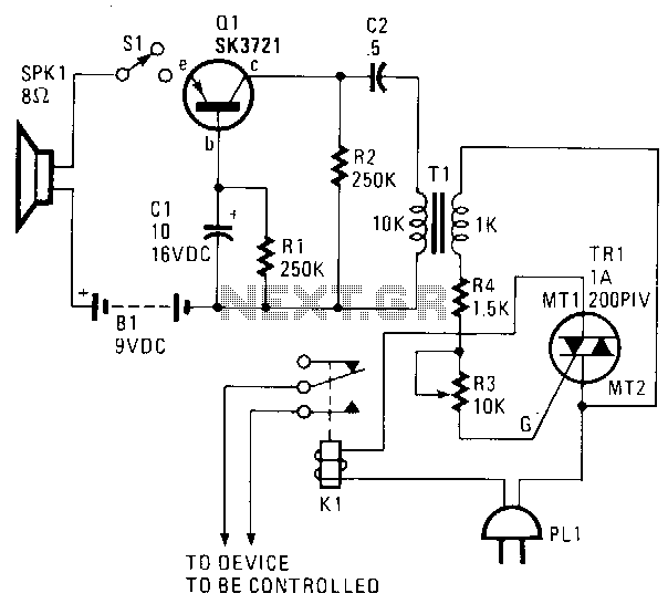
The sound captured by speaker SPKR1, functioning as a microphone, is transmitted to transistor amplifier Q1. The output from Q1 is connected to coupling transformer T1, which is utilized to activate the gate circuit of Triac TR1. Additionally, TR1...
The following touch switch circuit utilizes a CA3240 dual BiMOS operational amplifier to detect small currents flowing between the contact points on a touch plate. The touch switch circuit employs a CA3240 dual BiMOS op-amp, which is known for...
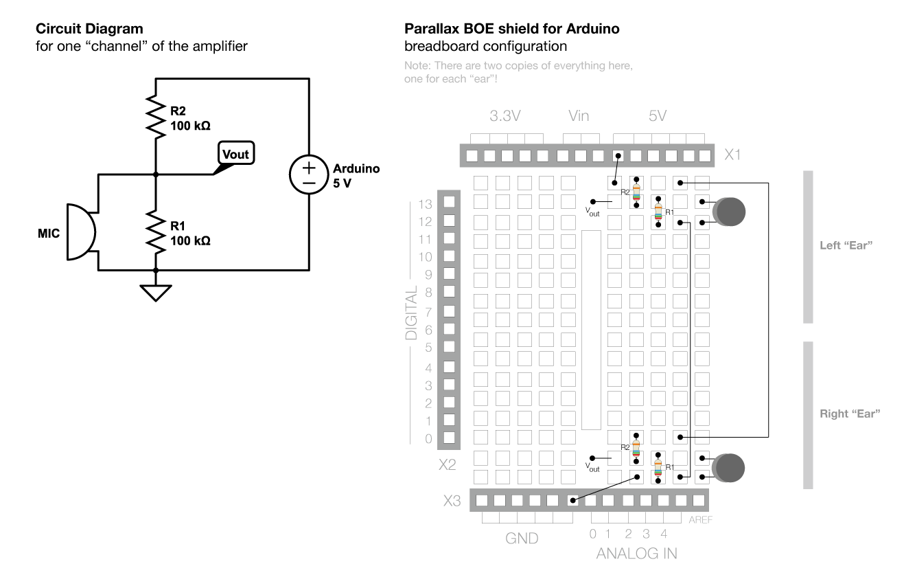
The voltage across the two pins of a microphone fluctuates based on the input sound. To amplify this signal for the Arduino to read it, a complex circuit is required. Initially, the voltage changes from the microphone are small...
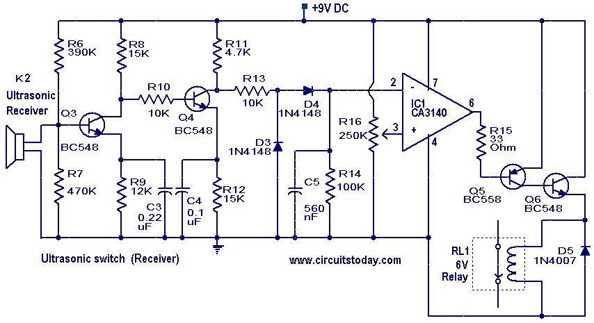
This is a relay circuit that detects the presence of sound to activate the relay. This sound-controlled relay can be utilized as a voice-operated switch or for controlling lights. The sound-activated relay circuit typically employs a microphone or a sound...