
The Synthetic Psychology of Sound Localization
A comprehensive understanding of the microphone circuit involves several key components and steps. The microphone serves as a transducer that converts sound waves into electrical signals. These signals are usually very weak, necessitating amplification for effective processing by microcontrollers like Arduino. The voltage divider circuit plays a crucial role in adjusting the initial microphone output to a more manageable level.
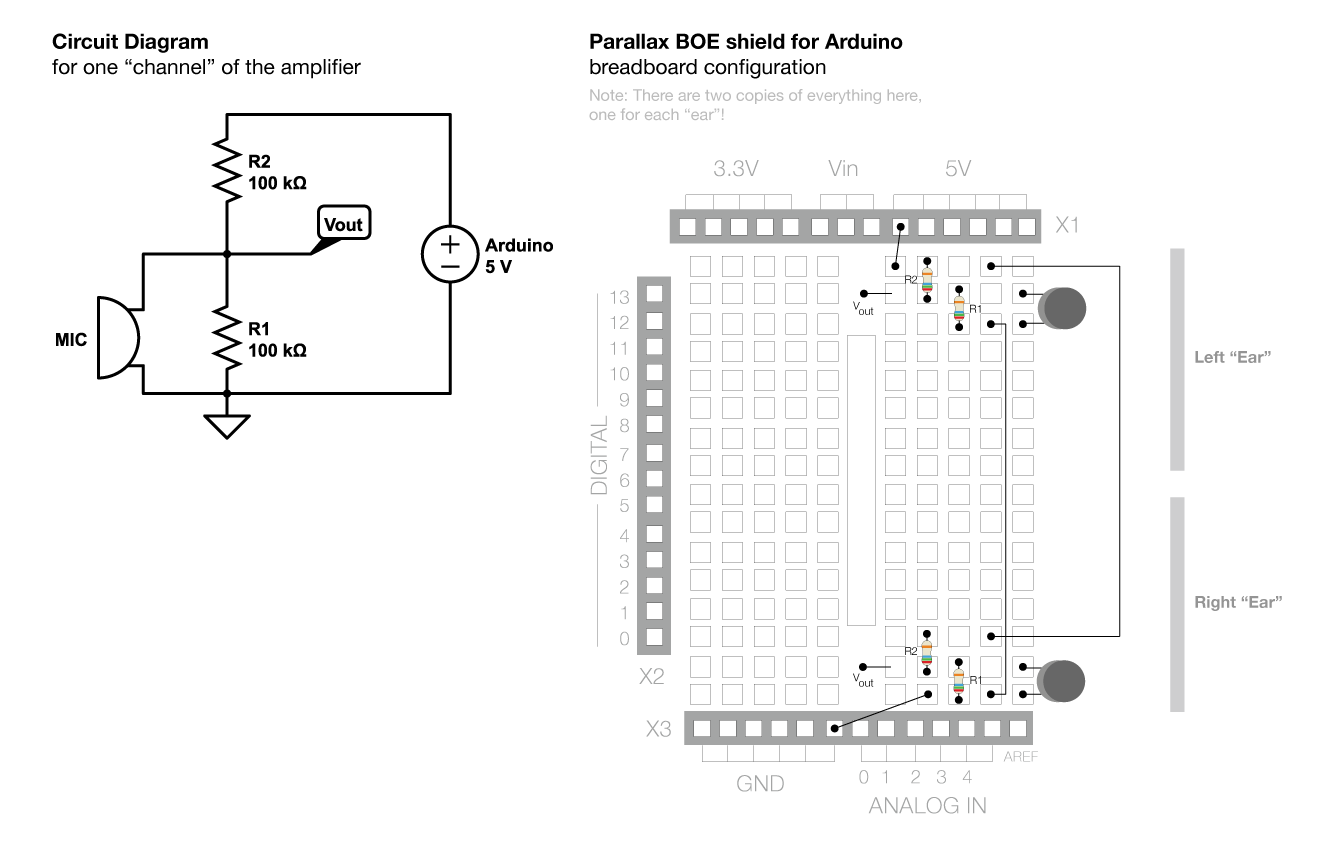
In this setup, the voltage divider consists of two resistors, R1 and R2, connected in series between the positive voltage source and ground. The output voltage (Vout) is taken from the junction between the two resistors. The formula for Vout in a voltage divider is given by:
\[ V_{out} = \frac{R2}{R1 + R2} \times V_{in} \]
By selecting R1 and R2 of equal resistance (for instance, 100 kΩ), Vout will be half of Vin, which is 2.5V when Vin is 5V. This configuration ensures that the output voltage is well within the operational range of the Arduino's analog input pins.
To integrate the microphone, it is connected in parallel with R1. This configuration allows the microphone to influence the voltage at Vout, causing it to fluctuate in response to sound. The output from the microphone will typically be less than 2.5V due to its own internal resistance and the characteristics of the sound waves it detects.
To ensure that the Arduino can accurately read these fluctuating voltages, an operational amplifier (op-amp) circuit may be employed. The op-amp can be configured to amplify the small voltage changes from the microphone significantly, allowing for better resolution and sensitivity.
The final stage of the circuit includes another amplification step to ensure that the output signal is within the 0-5V range required by the Arduino. This can be achieved through additional op-amp configurations or by using a dedicated audio amplifier module.
In summary, this microphone circuit, involving a voltage divider and amplification stages, enables the Arduino to effectively read sound signals, facilitating various applications in sound detection and processing.Although the voltage across the two pins of our microphone will fluctuate based on the input sound, we would like to amplify this so that the Arduino can actually read the signal. This can be a bit of a complex circuit to think about at first to we will build it up slowly. This figure gives an overview of what the circuit will do: First, the volta ge changes due to the mic (step 3 in the figure) are relatively small (fractions of a millivolt usually) we would first like to move them into a better range to use as input to our amplifier (step 4 in the figure). We`ll do this a couple times in the lab and refer to it as "stepping up" the signal, since we are changing the average voltage value without changing the variance.
The amplifier stage will "turn up the volume" on the voltage changes by making them span a larger range (step 5). Thinking back to your statistics class, this step does effect the variance! The output of the amplifier will be centered at 0V and range positively and negatively. However the Arduino can only read positive values in the range 0-5V. Thus, in the final stage, we will "step up" the signal again to range between 0V and 5V (step 6 in the figure) which is the type of input signal that the Arduino analogRead() function is designed to measure (step 7 in the figure).
In order to add the microphone to the Arduino, we need a basic microphone circuit that provides voltages with the appropriate values. This will cover steps 1-4 in the overview above. A classic way to do this is with a "voltage divider" circuit (see below). A voltage divider simply involves a voltage source (e. g. , battery, or in our case the +5V pins on the Arduino chip) and two resistors. The resistor are connected in series (i. e. , in a row or sequence. if the wires are the resistors "arms", imagine they are holding hands in a line). The voltage we are interested in will be measured at the middle point between the two resistors (we`ll call this value Vout).
The value of Vout as a function of Vin (the voltage provided by the battery or Arduino) is given by the equation on the right. We will choose R1 and R2 so they are the same value, thus Vout will be 1/2 Vin. However, other fractions are also possible by choosing the right resistor. This circuit is so popular, it even has its own Wikipedia page ! The figure below (click to enlarge) shows the abstract circuit diagram for one voltage divider circuit, the theoretical relationship between the resistor values, the input voltage (Vin), and the output voltage (Vout), along with an example of two voltage dividers wired up on you Ardunio breadboard.
Ignore the colors on the resistors, those are just for illustration. As indicated in the circuit, you should select 100KOhm resistors. This page has some helpful info about reading the colors stripes on the side of a resistor element so you can identify the value. We can add to it by putting our microphone in parallel with the first resistor (R1). Parallel means that the "arms" of the component are holding both hands like you would if you were slow dancing with someone.
Once the microphone is hooked up the voltage will be a little lower than 2. 5V at Vout terminal due to the influence of the microphone circuit which has it`s own resistance. In addition, the voltage at each Vout will now fluctuate (in fractions of millivolts) due to the sound pressure being registered by the microphone element. Although you could connect the Vout terminals from the last circuit above directly to the "ANALOG IN" pins on the breadboard (A0-A4 at the bottom right) and then read the voltages from them using analogRead() in your Ardunio code, the voltages fluctuations coming from this microphone circuit are too small to be read reliably except maybe for really loud sounds.
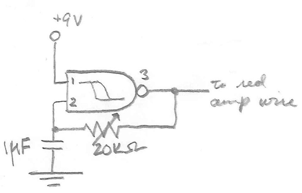
Thus, we need to give our robot a hearing aid (i. e. , amplifier) which, like the amplifier in a car stereo, makes the sound "louder" (but in te 🔗 External reference
Related Circuits
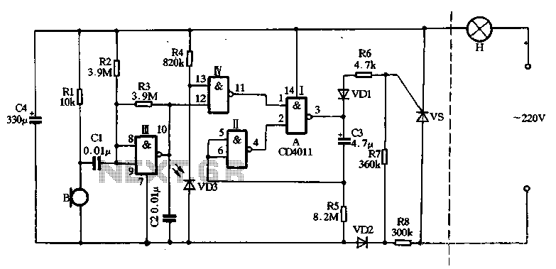
The main circuit utilizes a two-input NAND gate composed of four digital integrated circuits. This includes a NAND gate microphone amplifier circuit, a light control mechanism using an "AND gate," and a monostable delay control circuit formed by NAND...
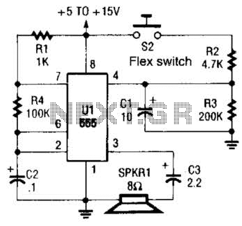
This is a cross-sectional diagram of a flex switch. They can be used as pushbuttons or even position sensors. This schematic diagram shows an oscillator, which is used as an alarm sounder, triggered by a flex switch. The flex switch...
This is a less polished version of Handmade Electronic Music, featuring nearly identical content and available for free. Notably, refer to Chapters 18 and 20. The layout consists of conductive metal strips beneath the perforations of the breadboard. Typically,...
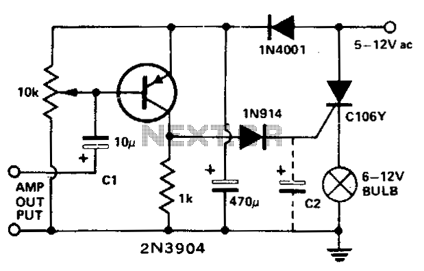
This circuit modulates a light beam using audio signals from an amplifier's output. By adjusting the 10 K potentiometer to a value slightly less than the Vbe of the transistor, the circuit operates as a peak detector. This configuration...
This circuit is designed to trigger on a 1 kHz tone. To change this frequency, refer to the table below, then change the resistor and capacitor values accordingly. More: all resistors are 5 or 10 percent tolerance, 1/4-watt; all...

The generated alternating current (AC) at both ends of the voltage is adjusted after being rectified to supply the motor armature windings, allowing for speed adjustments of a 15W lamp. It is noteworthy that despite the freewheeling role of...