
counter down timer circuit

This countdown timer circuit effectively combines the functionality of a 555 timer IC and a 14-stage binary ripple counter to create a versatile timing solution. The 555 timer is configured in astable mode, generating a consistent square wave output that serves as the clock signal for the 4020 counter. The choice of the 4020 counter allows for a broad range of timing applications, as it can count up to 16,384 clock cycles, translating to significant time delays when configured correctly.
The power-on reset circuit, consisting of capacitor C3 and resistor R4, ensures that the counter begins in a known state upon power-up. The diode D1 plays a crucial role in discharging C3 when the circuit is powered down, preventing any unwanted counts during subsequent power cycles. This feature enhances the reliability of the timer.
Adjustable resistors (R1) and capacitors (C1) provide flexibility in setting the timing intervals, allowing for customization based on specific application requirements. The configuration of the BC547 transistors facilitates the relay operation, providing the ability to select between different relay action modes via a jumper. This adaptability makes the circuit suitable for various applications, including automated control systems, timers for household appliances, and industrial timing solutions.
Overall, the design integrates fundamental electronic components to achieve a functional and adjustable countdown timer, demonstrating the versatility and utility of the 555 timer and binary counters in practical applications.This circuit is design of the counter timer that using countdown calculation. This circuit is using 555 IC as main control. 555 IC is a counter IC and a transistor switch to activate a relay either ON/OFF (mode selected by a jumper) as soon as the counting period is over. The circuit consists of an oscillator, a ripple counter and two switching tr ansistors. This is the figure of the project circuit. The 555 is configured in the standard astable oscillator circuit designed to give a square wave cycle at a period of around 1 cycle/sec. The output pulse from pin 3 of the 555 is fed to the clock input pin 10 of the 14-stage binary ripple counter, the 4020 (or 14020.
) Operation of the circuit is explained in next. In this circuit C3, R4 and D1 are arranged as a power-on reset. When power is applied to the circuit C3 is in a discharged state so pin 11 will be pulled high. C3 will quickly charge via R4 and the level at pin 11 falls thus enabling the counter. The 14020 then counts clock pulses until the selected counter output goes high. D1 provides a discharge path for C3 when the power is disconnected. You can change the components values of R1 and C1 to set the 555 count frequency to more than 1. 0 Hz. If you change the count to 10 seconds then a maximum timer delay of 81920 seconds, or 22. 7 hours, can be obtained. The output from the 4020 goes to a transistor switch arrangement. Two BC547 are connected so that either switching option for the relay is available. A jumper sets the option. The relay can turn ON when power and counting start then turn OFF after the count period, or it can do the opposite. The relay will turn ON after the end of the count period and stay on so long as power is supplied to the circuit.
Note that the reset pin of the 555 is connected to the collector of Q1. This enables the 555 during the counting as the collector of Q1 is pulled low. 🔗 External reference
Related Circuits
Coin detector and counter: How to detect different types of coins from their effect on an oscillating magnetic field. A coin detector and counter operates by utilizing the principles of electromagnetic induction to identify and differentiate between various types of...
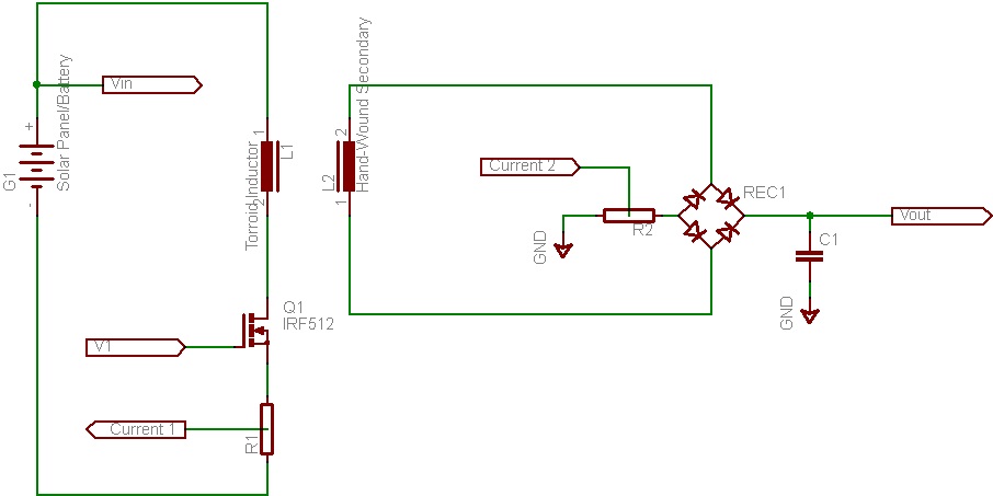
This document discusses the future direction of the Free Charge Controller project and proposes a new solar charge controller circuit. The Free Charge Controller project aims to enhance the efficiency and effectiveness of solar energy management systems. The proposed solar...

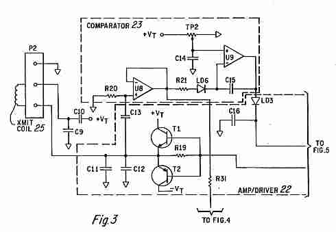
Frequency shift keying (FSK) is a widely used digital modulation technique for data transmission. Common applications of FSK modulation encompass both wired and wireless data transmission, as well as infrared remote controls for consumer electronic devices. FSK demodulation can...
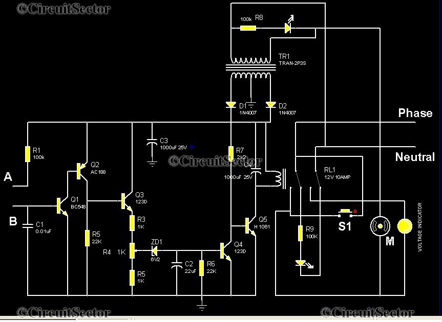
This is an automatic water tank controller designed to manage the operation of a water pump using a 12V 10A relay. When the water level in the tank creates a short circuit between points A and B in the...
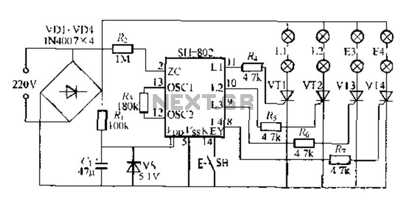
A digital integrated circuit simplifies the response process significantly. The diagram illustrates a circuit comprising four responder groups. The digital integrated circuit described serves as a crucial component in various electronic systems, primarily focusing on enhancing response efficiency. It comprises...
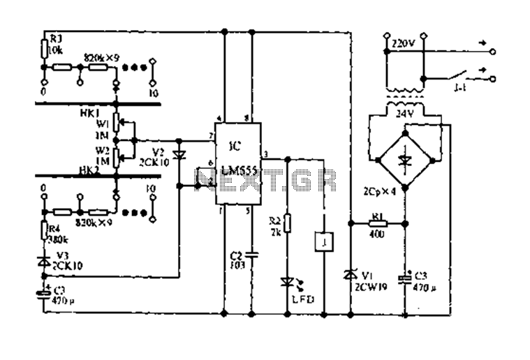
The circuit diagram for an electric start and stop timer is illustrated in the following cycle. It utilizes the LM555 integrated circuit configured as an adjustable duty cycle multivibrator. The circuit includes components C3, KH1, W1, KH2, and W2,...