
Sound-Level Meter
The NE604 signal-strength indicator circuit is designed for effective audio signal processing, specifically for measuring sound levels in decibels. The internal logarithmic converter within the NE604 provides a linear representation of the decibel scale, making it suitable for both analog and digital readouts. The electret microphone serves as the primary transducer, converting sound waves into electrical signals. Its built-in buffer stage ensures that the microphone output is stable and suitable for further processing.
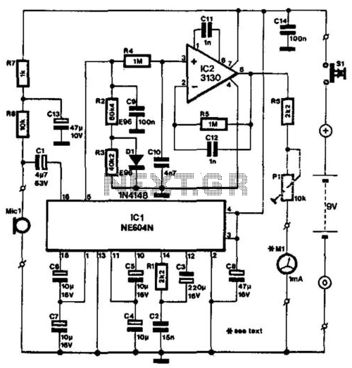
Resistors R7 and R8, along with capacitor C13, play a crucial role in supplying the necessary voltage to the microphone's buffer stage, ensuring optimal performance. The NE604's output current capability (0 to 50 mA at pin 5) results in a corresponding voltage across resistors R2 and R3, which is critical for achieving the desired output range of 0 to 5 V. This range effectively corresponds to a sound level of 70 dB, allowing for a comprehensive understanding of ambient noise levels.
Temperature compensation is achieved through a combination of resistors and a diode, which stabilizes the circuit against variations in temperature that could affect the performance of the resistive components. The filtering stage, comprising R4, C9, and C10, is essential for removing any unwanted ripple from the output voltage, thereby ensuring that the buffered signal from IC2 is clean and accurate for measurement purposes.
The output from IC2, which is connected to the indicating instrument, can be adjusted for full-scale deflection at 4 V. This adjustment is critical for accurate readings, and the calibration process may require either a calibrated reference instrument or knowledge of the loudspeaker's efficiency. The indication provided by the meter is meant to serve as a guideline rather than an absolute measurement, highlighting the circuit's design focus on relative sound level indication rather than precise quantification. The absence of a filtering mechanism for absolute measurements reflects a design choice aimed at simplifying the circuit while maintaining functionality. The NE604"s signal-strength indicator section is used, based on an internal logarithmic converter. This enables a linear decibel scale so that the moving-coil meter (shown in the diagram) can be replaced by a digital instrument. The signal source is assumed to be an electret microphone that converts ambient noise into an electrical signal.
Because this type of microphone normally contains a buffer stage, R7, R8, and C13 have been included to provide the supply voltage for this stage. The NE604 delivers an output current (at pin 5) of 0 to 50, which causes a potential difference across R2 + R3 of 0 to 5 V.
The input and output signal range is equivalent to a sound range of 70 dB. lb compensate for the effects of temperature changes, the required resistance of 100 KOhmhm is formed by two resistors (R2 and R3) and a diode (Dl). Any ripple remaining on the output voltage is removed by R4/C9/C10 before the output is buffered by IC2.
The indicating instrument, here a moving-coil meter, is connected to the output (pin 6) of IC2 via a series resistance, R^ + . The preset is adjusted to give full-scale deflection (FSD) for an output voltage of 4 V. Calibrating the meter is a little tricky, unless you have access to an already calibrated instrument.
Otherwise, if you know the efficiency of your loudspeaker, that is, how many decibels for 1W at 1 m, you can use that as reference. The scale of the meter can then be marked with the (approximate) value. In any case, the meter deflection must at all times be seen as an indication, not as an absolute value: it was not thought to be worthwhile to add a filter to the circuit to enable absolute measurements to be made.
🔗 External reference
Related Circuits
Digital speedometers are typically found in luxury vehicles and high-performance motorcycles. However, in the event of a malfunction in a mechanical speedometer, an alternative solution is necessary. This digital speedometer displays speed and distance in kilometers for both motorcycles...
While it may lack the aesthetic appeal of traditional mercury barometers featuring elongated glass tubes mounted on intricately carved wooden bases, the Torricelli barometer described here serves as a functional equivalent and electronic replica of the original Torricelli barometer....
The circuit utilizes two quad voltage comparators (LM339) to illuminate a series of eight LEDs that indicate volume levels. Each of the eight comparators is biased at increasing voltages determined by a voltage divider, allowing the lower right LED...
We are OUT OF STOCK on the surplus brushless DC motor we used to build this project, and since it's surplus we cannot get any more. The resistor and capacitor values listed in the schematic and on the PC...
The differential thermometer utilizes two probes to display the temperature difference between them instead of indicating the precise temperature. It employs a conventional meter as an indicator and has a total range of -10°C to 20°C. The differential thermometer operates...
The proximity detector detects the movement of PC board pieces as the wheel rotates, generating an output signal with a clear transition between high and low voltage levels, making it suitable for triggering counting or processing circuits. Following this...