
led vu meter
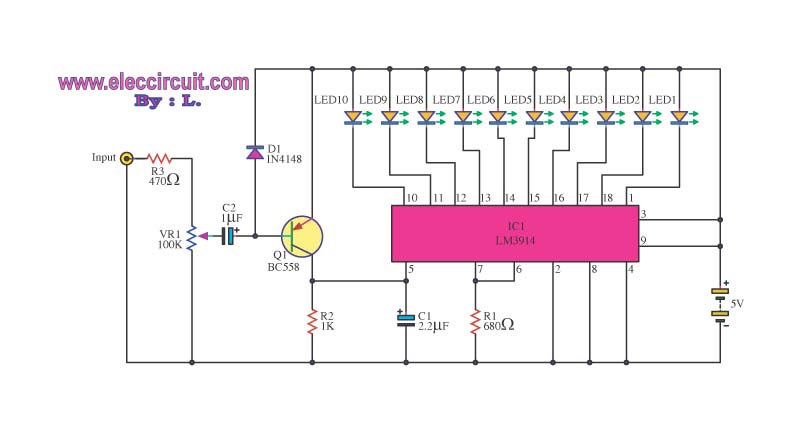
The circuit employs the LM339, a quad comparator that is well-suited for low-voltage applications. The comparators are configured to compare the input voltage against reference voltages generated by the voltage divider network. This network consists of resistors arranged to create a series of reference voltages, each incrementally higher than the last. The first comparator activates when the input voltage exceeds 400 millivolts, turning on the first LED. Subsequent comparators are set to activate at progressively higher voltage thresholds, effectively doubling the power level represented by each LED.
The power levels indicated by the LEDs are crucial for applications where visual feedback of volume is necessary, such as in audio equipment. The design allows for a clear visual representation of the audio power levels, making it easier for users to monitor and adjust settings. The adjustable input control provides flexibility, enabling the circuit to be tuned for different audio systems or user preferences.
In terms of implementation, care must be taken to ensure that the voltage divider is accurately set to achieve the desired thresholds. The use of precision resistors is recommended to maintain consistency in the reference voltages. Additionally, the circuit should be tested under actual operating conditions to validate its performance and responsiveness to varying input levels. Proper power supply decoupling is also advised to mitigate any potential noise that could affect the comparator operation.The circuit below uses two quad voltage comparators (LM339) to illuminate a series of 8 LEDs indicating volume level. Each of the 8 comparators is biased at increasing voltages set by the voltage divider so that the lower right LED comes on first when the input is about 400 millivolts or about 22 milliwatts peak in an 8 ohm system.
The divider vol tages are set so that each LED represents about twice the power level as the one before so the scale extends from 22 milliwatts to about 2. 5 watts when all LEDs are lit. The sensitivity can be decreased with the input control to read higher levels. I have not built or tested this circuit, so please let me know if you have problems getting it working.
The power levels should be as follows: 🔗 External reference
Related Circuits
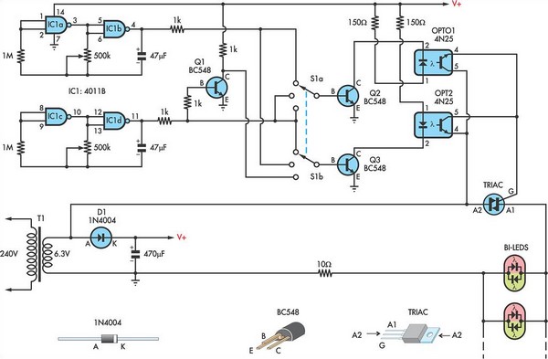
This circuit utilizes low-voltage AC to power a string of approximately 50 bi-color LEDs, with two LEDs connected in inverse parallel. The power supplied to the LEDs is managed by a Triac and two optocouplers, whose phototransistors are also...
This is a simple light-running circuit synchronized with music. The circuit is straightforward, operating in mono, and requires only a few components. It can be connected to the output of a CD player. The described circuit utilizes a basic audio...
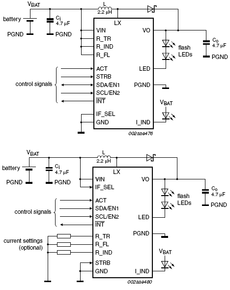
This device offers an extended battery life and operates with low power consumption. Additional features include battery and LED overload protection, seamless operation with safeguards against overtemperature, overvoltage, a timeout function, undervoltage lockout, and feedback short-circuit protection. The device is...

Transmitter RF Output LED Indicator Circuit Diagram. This RF output detector circuit, which includes a visual indicator, can be useful for an RF application. The transmitter RF output LED indicator circuit is designed to provide a visual representation of the...

Before using LEDs, it is advisable to test them. An LED tester allows for testing even in low light conditions. LEDs are available in various shapes and colors, with some featuring clear, colorless packages and others having colored plastic...
The operating principle of the circuit is very simple. The first LED D1 is placed in series with the resistor R2 and diode D4. An only be lit this LED indicates that the battery is overcharged. For this reason,...