
Homemade Easter Egg Anemometer
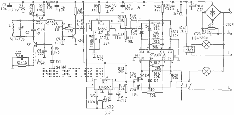
The circuit described relies on a specific surplus brushless DC motor, which is no longer available. The design of the circuit is tailored to the electrical characteristics and operational parameters of this particular motor, including its voltage and current ratings. The resistor and capacitor values specified in the schematic are integral to the performance of the circuit, as they are selected based on the motor's electrical properties.
In a typical brushless DC motor circuit, the motor is driven by a controller that manages the switching of power to the motor phases. The controller typically employs a pulse-width modulation (PWM) technique to regulate speed and torque. The resistors in the circuit may be used for current sensing, feedback, or biasing, while the capacitors could serve to filter noise, stabilize voltage levels, or provide decoupling.
When designing or modifying a circuit that uses a specific motor, it is essential to consider the impact of substituting the motor with a different model. Variations in motor specifications can lead to improper operation, overheating, or failure of components. Therefore, if a replacement motor is required, it is advisable to analyze its characteristics and adjust the resistor and capacitor values accordingly to ensure compatibility with the existing circuit design.
In summary, the circuit's performance is closely tied to the specific brushless DC motor used, and careful consideration must be given to any future implementations or modifications that involve different motor components.We are OUT OF STOCK on the surplus brushless DC motor we used to build this project, and since it`s surplus we cannot get any more. The resistor and capacitor values listed in the schematic and on the PC board plan depend on using this exact same motor.
🔗 External reference
Related Circuits
The reason for this project was to facilitate a quick installation for a local friend 10 km away, enabling the start of real-life testing to identify and resolve bugs and problems before releasing it to other users. The software...
This ultrasonic anemometer is designed for the two-dimensional measurement of horizontal wind speed components and wind direction, as well as virtual temperature. Due to its high measurement rate, the device effectively captures gusts and peak values without delay. The...
When the infrared receiver tube PH302 receives a signal from the remote control, the CX20106A selected frequency amplifier outputs a low-frequency signal. The low-level signal charges capacitor C through diodes D and R, causing the negative side potential of...
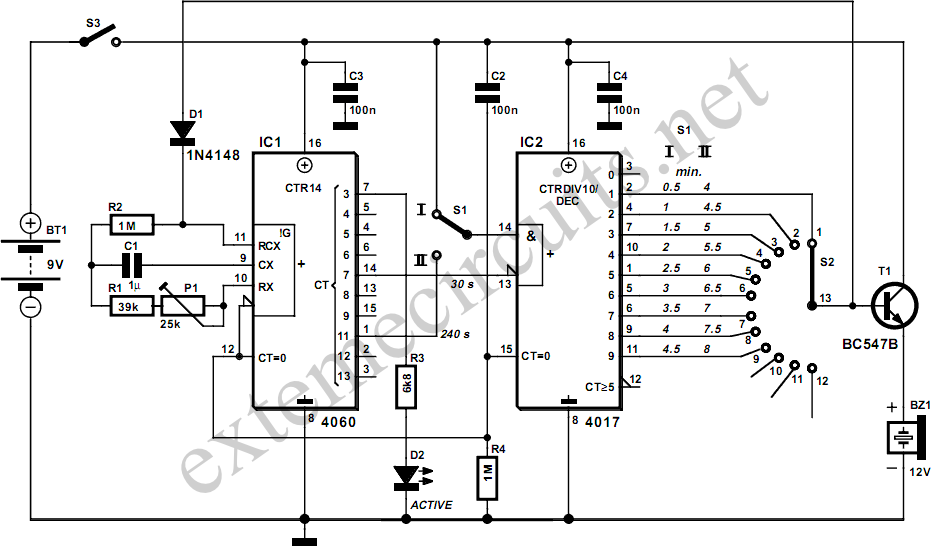
This egg timer, which is both simple and functional, demonstrates that it is not essential to use a microcontroller for everything these days. The circuit consists of only two integrated circuits (ICs) from the standard 4000 logic family, a...
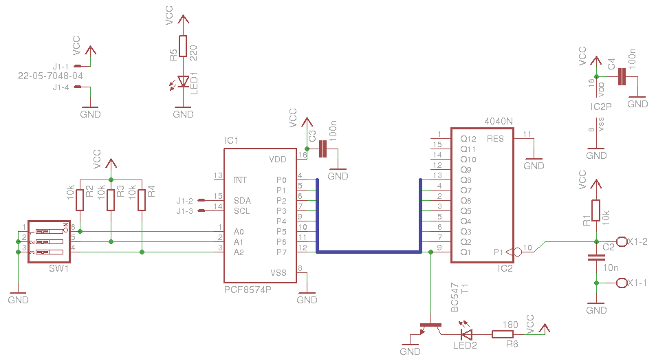
The board is relatively simple and is based on a PCF8574, which provides the output of a CD 4040 counter to the I2C bus. A DIP switch is included to select the PCF8574 address, along with some LEDs for...
The Bug-Eyed Eggliner project involves creating a whimsical animated figure with large, illuminated, and movable eyes. The project utilizes a combination of wooden balls for the eyes, a PICAXE microcontroller for control, and a servo mechanism to achieve eye...