
Sound operated flip flop

The described circuit utilizes a condenser microphone to detect sound waves, converting them into an electrical signal. This signal is then processed by the first two operational amplifiers within the LM324 IC, which serve to amplify the weak audio signal captured by the microphone. The amplification is crucial as it ensures that the signal is strong enough for further processing.
The third operational amplifier in the LM324 is configured as a level detector. This configuration allows it to compare the amplified audio signal against a predetermined reference voltage applied to pin 5. When the sound level surpasses this reference, the output of the third op-amp at pin 7 transitions to a high state. This transition serves as a trigger for the CD4027 Flip Flop IC.
The CD4027 is a dual J-K flip-flop, which means that it can toggle its output state based on the triggering signal received. Each time the output from the level detector goes high, the flip-flop changes its state, effectively toggling the output pins (pins 1 and 2). This functionality can be used in various applications, such as sound-activated switches, where the presence of sound can control electronic devices or systems.
To ensure proper operation, the circuit may require additional components such as resistors and capacitors for biasing and stability. The design should also consider the power supply requirements for both the LM324 and CD4027 ICs, ensuring that they operate within their specified voltage ranges. Overall, this circuit exemplifies the integration of audio detection and digital logic control in electronic design.Here given is a circuit in which the status of the output pins of a Flip Flop IC can be toggled by using sound. A condenser microphone is used for picking up the sound. The first two op-amps in the IC1 LM 324 is used to amplify the sound picked by the condenser microphone.
The third op-amp inside LM 324 is wired as a level detector. When ever the voltage produced due to sound have a level more than that of the reference voltage at pin 5 of the third op-amp, its output (pin 7) goes high, triggering the flip flop IC1 CD 4027. As a result the state of the output pins of CD 4027 ( pin 1 & pin 2) toggles for each burst of sound.
🔗 External reference
Related Circuits
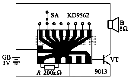
The KD9562 music octave circuit is an analog sound circuit capable of producing various sound effects including rifle shots, space shots, game console sounds, dual-tone doorbells, bomb explosions, machine gunfire, and ambulance sirens. The main electrical parameters are as...
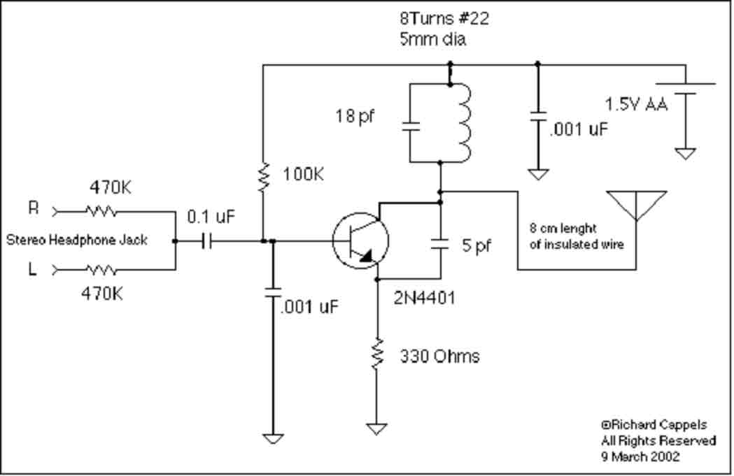
This device is designed to rebroadcast the output of a CD player, television receiver, or radio receiver. It allows for mobility within the home, enabling users to enjoy their favorite programs without being tethered to the source. The effective...
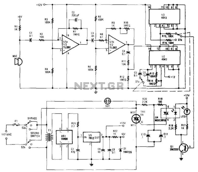
This circuit provides either latched switching or timed switching. U1A and U1B provide audio amplification from the microphone. U2 is a retriggerable monostable multivibrator. S1A and S1B select either U3, a flip-flop, or U2. R13 and R14 allow a...
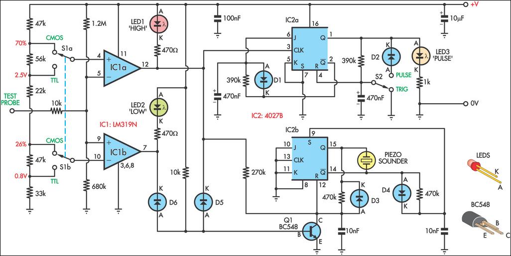
This logic probe can be configured to operate on either TTL or CMOS logic levels using switch S1. A series of resistors connected to switch S1 establishes the threshold levels for a window comparator made up of IC1a and...
The construction of this complex circuit will yield the pleasure of generating nearly unlimited sound effects. The circuit is capable of producing a variety of sounds, ranging from the heavy chopping of helicopter blades to the delicate chirping of...
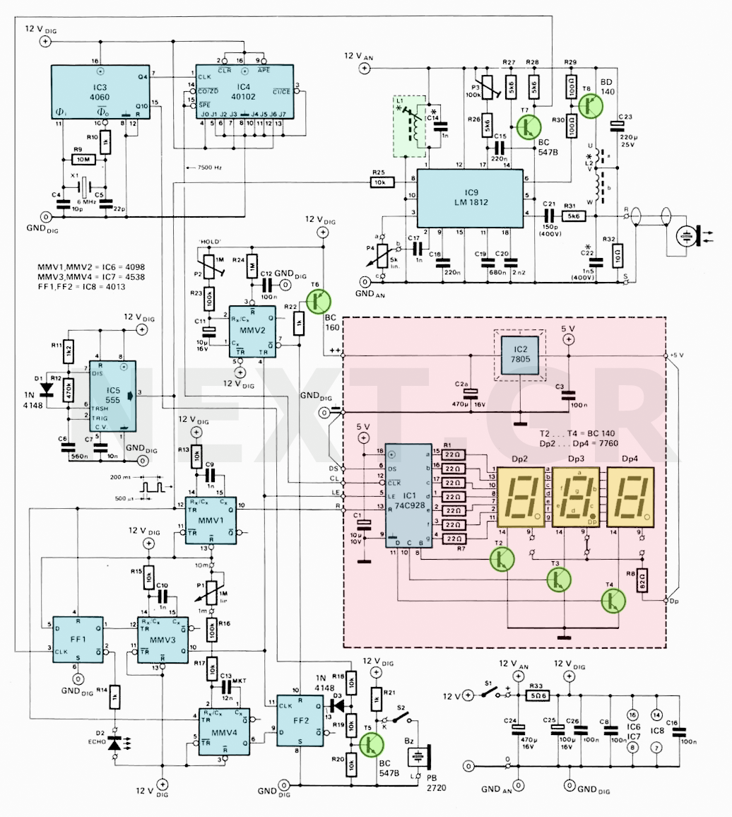
In the past, depth measurement of the sea bottom was performed using a "bullet," which was a heavy lead object lowered into the water from a calibrated rope. When the bullet reached the seabed, the depth could be read...