
Sound-Activated Switch
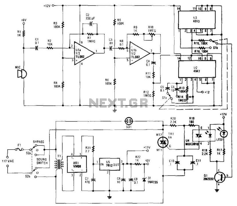
This circuit is designed to operate in two distinct modes: latched switching and timed switching, providing flexibility for various applications. The audio input from a microphone is amplified by operational amplifiers U1A and U1B, ensuring that the signal is sufficiently strong for further processing.
The core of the timing functionality is implemented using U2, a retriggerable monostable multivibrator, which allows the circuit to generate a pulse of a specified duration upon receiving a trigger signal. The timing characteristics are adjustable through resistors R13 and R14, which set the delay interval between 6 to 60 seconds after the audio signal has ceased. This feature is particularly useful in applications where a delayed action is required post-signal detection.
Switches S1A and S1B serve as selectors, enabling the user to choose between the flip-flop configuration provided by U3 or the timing functionality of U2. This selection capability allows for the circuit's operation to be tailored to specific requirements, whether for maintaining a state until reset (latched mode) or for executing a timed response (timed mode).
Power supply requirements are met by BR1, U5, and their associated components, which convert the input voltage to the necessary levels for circuit operation. An alternative configuration using four silicon diode rectifiers arranged as a bridge can replace BR1, provided that the diodes are rated for at least 50V and 1A to ensure reliability under load conditions.
The output stage of the circuit is driven by transistor Q1, which activates optocoupler U4. This optocoupler provides electrical isolation and allows for safe interfacing with higher voltage components, such as triac TR1, which is responsible for controlling AC loads. This design ensures that the circuit can operate safely and effectively in controlling various devices based on audio input, making it suitable for applications in automation, security, and smart home systems. This circuit provides either latched switching or timed switching. U1A and UlB provide audio amplification from the microphone. U2 is a retriggerable monostable multivibrator. SI A and SIB select either U3, a flip-flop, or U2. R13 and R14 allow a 6- to 60-second timer delay after the sound ceases, in the timed mode. BR1, U5, and associated components form a power supply. Ql drives optocoupler U4 and triggers triac TRl. -If desired, four silicon diode rectifiers connected as a bridge can be substituted for BR1. Just make certain the diodes are rated at least 50V, 1A. 🔗 External reference
Related Circuits
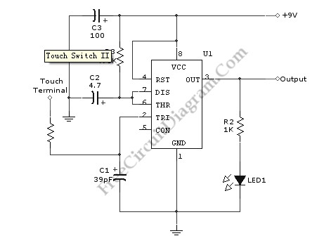
Utilizing the specified values depicted in the schematic diagram, this circuit features a timed ON period of 4 seconds. The ON time is governed by the values of capacitor C2 and resistor R3; increasing either C2 or R3 will...
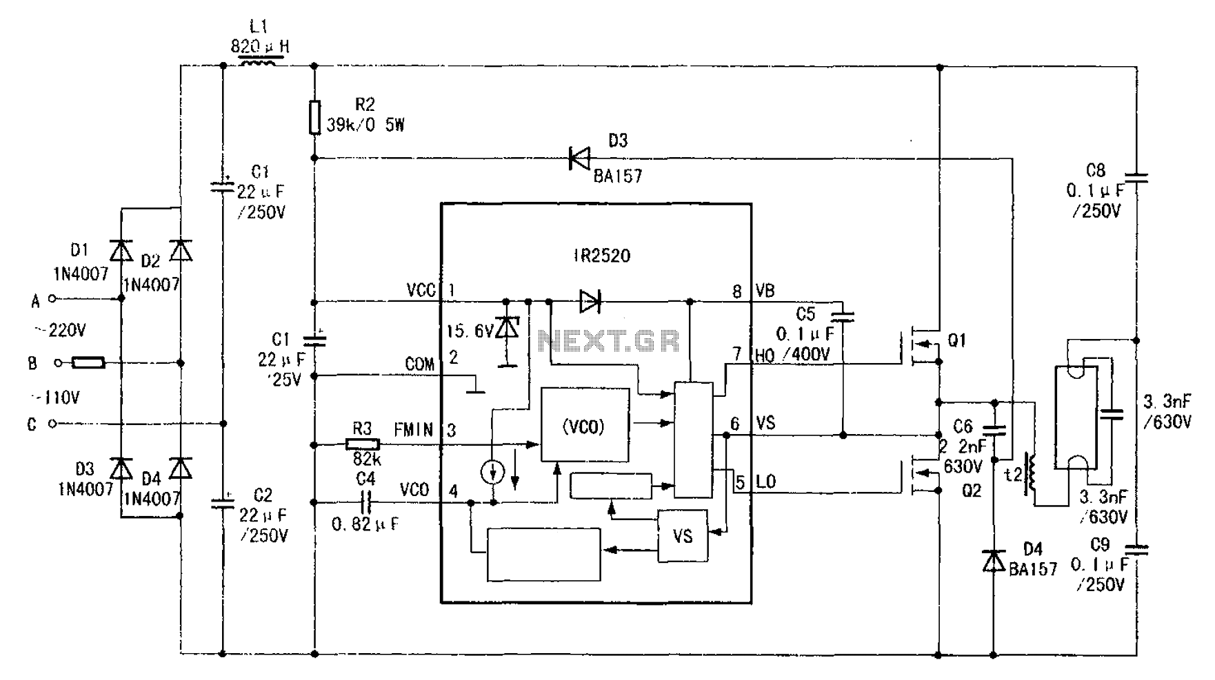
The adaptive zero voltage switching electronic ballast schematic diagram utilizes the IR2520 primarily for driving fluorescent lamps of 40W or less. The parameters of components such as Q1, Q2, L2, and C7 vary depending on the rated power of...
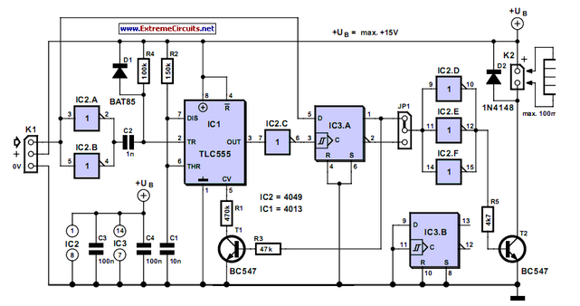
It is sometimes necessary for a remote control (RC) model to incorporate a switching functionality. This can include features such as lights on a model. In the context of remote control models, incorporating switching functionality can significantly enhance user experience...
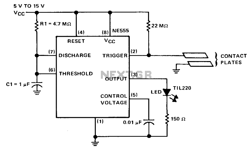
The circuit consists of a NE555 monostable timer, with a unique triggering method. The trigger input is held at a high voltage level by a 22-ohm resistor. When the contact plates are engaged, the operator's skin resistance decreases the...
The Light Switch with Relay is a series of electronic switches that are controlled by light intensity. This circuit can automatically control lighting, turning the lights on when ambient light levels decrease. The threshold for light activation in the...
This analog switch utilizes the 2N4860 JFET, which features a low on-resistance (rON) of 25 ohms and minimal leakage current. The LM102 acts as a voltage buffer in the circuit. It is designed to be adaptable for use in...