
Sound operated two-way switch

The described circuit employs a sound sensor that detects acoustic signals above a certain threshold. When a sound, such as a clap, is detected, it triggers the Schmitt trigger formed by transistors Q2 and Q3. This configuration ensures that the output is clean and free from noise, providing a stable signal to the subsequent stages of the circuit. The Schmitt trigger outputs a high or low signal based on the input sound intensity, effectively converting the analog sound signal into a digital signal.
The JK flip-flop serves as a bistable multivibrator, which can maintain one of two stable states. The clock input (pin 12) receives the output from the Schmitt trigger, causing the flip-flop to toggle its output state with each detected sound pulse. This toggling action allows for the relay to be switched on with the first clap and off with the second clap, enabling a simple yet effective control mechanism.
Transistor Q4 is utilized to drive the relay, allowing the circuit to control larger loads that the flip-flop output alone cannot handle. When the JK flip-flop output goes high, Q4 is activated, energizing the relay coil and closing the relay contacts, which can then control external devices such as lights or motors.
In summary, the circuit effectively combines sound detection, digital signal processing, and relay control to create a responsive system that can be used in various applications, such as automated lighting systems or sound-activated devices. The careful selection of components and their configuration ensures reliable operation in response to acoustic stimuli.This circuit operates a relay each time a sound of sufficient intensity is made, thus one clap of the hands will switch it one way, a second clap will revert the circuit to the original condition. Q2 and Q3 form a Schmitt trigger. The JK flip-flop isoised as a bistable whose output changes state every time a pulse is applied to the clock input (pin 12)
Q4 allows the output to drive a relay.
Related Circuits

This figure illustrates a one-of-two switch featuring a summing amplifier. The video source's line can be terminated either externally or internally to switch RO. With this termination resistor, a load change of less than 10 ohms will be perceived...

The 1-Wire Net, or MicroLAN (by Maxim-Dallas), is a straightforward method for connecting slow devices such as sensors, relay drivers, and switches using basic components. These components include a 1-Wire protocol handler, an interface to the external world, and...
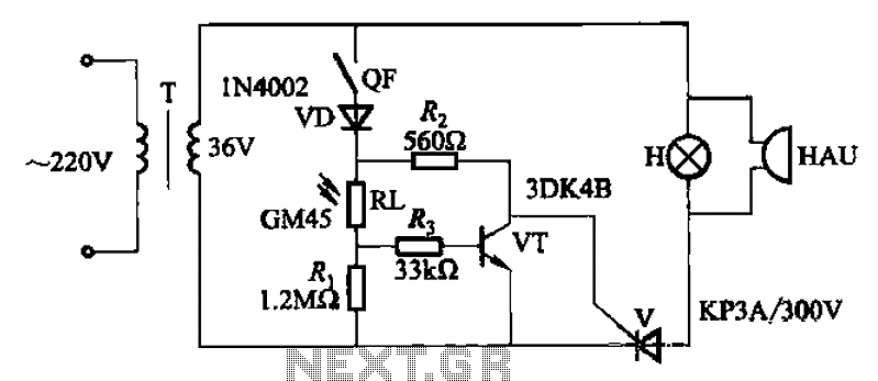
A school drama required lamps that automatically turned on and off in sync with the spotlights. The lamp switching system needed to be wireless, durable, reliable, simple, and cost-effective. With the stage and spotlights turned off, minimal light reaches...
Here we have three choices, with which we can make electronic switches that use our touch or pressing (push button). We thus exploit the very big resistance of entry, that present the gates CMOS. In the fig.1 we have...
High-voltage isolation switches must not be connected to loads that could create an arc, which may lead to a short circuit between the high-voltage bus and result in accidents that endanger both equipment and personnel safety. Consequently, high-voltage switchgear...
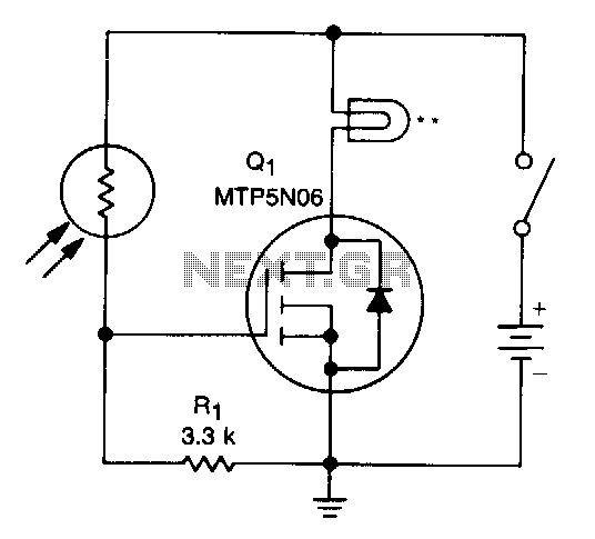
An optical toggle switch utilizing a single chip. This design employs a dual flip-flop integrated circuit (IC) CD4027 and incorporates a 555-based monostable circuit to generate input clock pulses. The circuit outlined here eliminates the need for this configuration. The...