
High-voltage isolation switch operation display circuit
High-voltage isolation switches play a critical role in electrical safety by preventing accidental connections that could lead to arcing and short-circuit conditions. The use of mechanical or electrical interlock devices is essential in high-voltage switchgear to ensure the proper operational sequence is maintained. This prevents the isolation switch from being engaged while the circuit breaker is still closed, which could otherwise lead to dangerous scenarios.
The operation display system enhances safety by providing visual feedback regarding the status of the isolation switch. The auxiliary contacts (QF) of the circuit breaker are utilized to monitor the state of the circuit breaker, ensuring that the isolation switch can only be operated when it is safe to do so. The photosensitive resistor (RL) serves as a feedback mechanism, detecting the position of the operating handle and ensuring that it is in the correct position before any operation can occur.
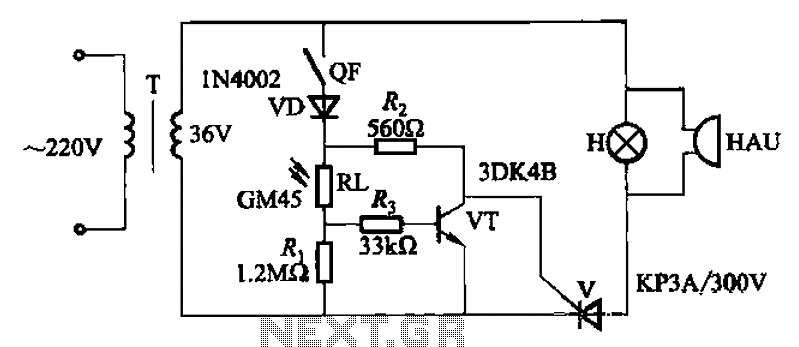
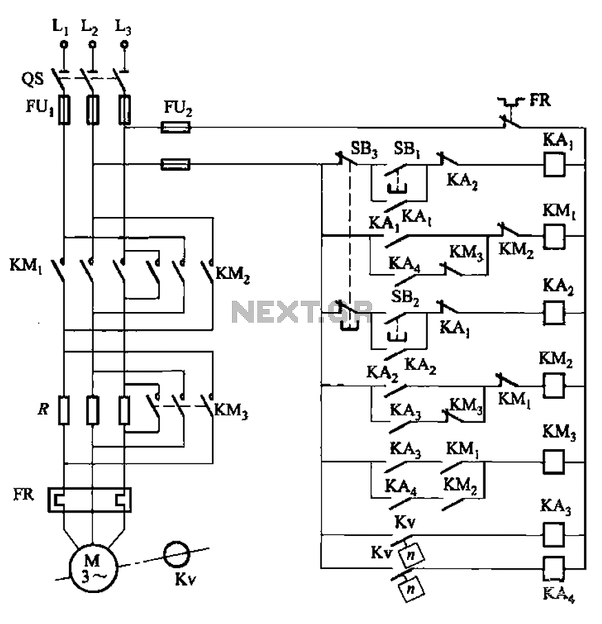
The display lamp (H) serves as a critical safety feature, alerting operators to any illegal operations or incorrect settings. This lamp is prominently placed on the cabinet door for easy visibility, ensuring that personnel can quickly ascertain the status of the isolation switch and take appropriate action if necessary. The integration of these safety features into high-voltage isolation switch designs is paramount for maintaining operational integrity and protecting both equipment and personnel in high-voltage environments. As we all know, high-voltage isolation switch is not allowed to meet with a load that would otherwise produce arc, causing a short between the high voltage bus road accident, e ndanger the equipment and personal safety. Therefore, high voltage switchgear are taking mechanical or electrical interlock device type, and only when high pressure circuit breaker, disconnecting switch to pull off; the circuit breaker in the closing position, must not be co-isolation switch. Operating sequence order can not be reversed. In order to avoid misuse of the accident, but also made high-voltage isolation switch operation display, the principle of the circuit shown in Figure 13-114.
Figure, QF of high voltage circuit breaker normally open auxiliary contacts; RL is photosensitive resistance, installed in the isolation switch operating handle; H display lamp, an outer cover that read illegal operation, non-suit words, installed in the cabinet door .
Related Circuits
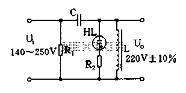
Easy exchange of magnetic saturation voltage regulator circuit The magnetic saturation voltage regulator circuit is designed to stabilize output voltage levels by utilizing magnetic saturation principles. This circuit typically employs a magnetic core, which operates in saturation to regulate...
To celebrate the hundredth design posted to this website and to fulfill the requests of many correspondents wanting an amplifier more powerful than the 25W MosFet, a 60 - 90W high-quality power amplifier design is presented here. The circuit...
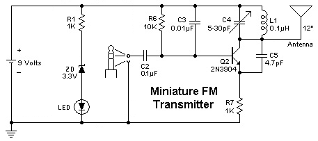
To replace a microphone with a 3.5" audio jack in a circuit, modifications will be necessary. The circuit currently utilizes an electret microphone, and adjustments must be made to accommodate the audio jack for audio transmission. The audio jack...
The circuit illustrated in Figure 3-130 differs from the circuit in Figure 3-129 in that when the stop button SB3 is pressed, the electric motor initiates braking. Furthermore, during both the startup and braking phases, the motor power lines...
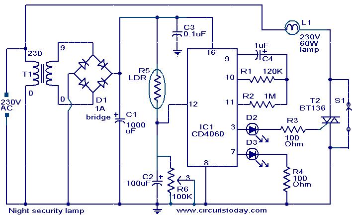
This simple circuit activates a light approximately two hours after midnight, a time when many robberies occur. The circuit is based on a CMOS IC 4060 to achieve the necessary timing. During the daytime, the light-dependent resistor (LDR) has...
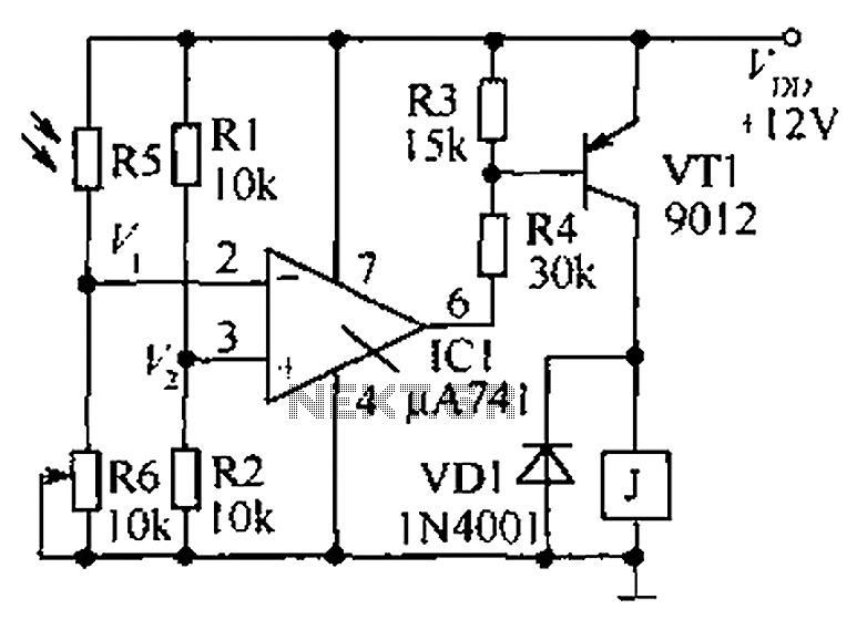
The circuit functions as a precision bright light control circuit, operating independently of variations in power supply voltage and ambient temperature. Resistors R1, R2, R6, and the photosensitive resistor R5 form a two-arm Wheatstone bridge. The precision bright light control...