
Optical toggle switch using a single Chip
The optical toggle switch circuit utilizes the CD4027 dual flip-flop IC, which is capable of toggling its output state based on the input clock pulses. The CD4027 consists of two independent flip-flops, allowing for versatile applications in digital logic designs. The integration of a 555 timer configured in a monostable mode serves to create precise timing pulses that act as the clock signal for the flip-flops.
In this configuration, the output of the 555 timer can be connected to the clock input of the CD4027, where each pulse from the timer will toggle the state of the flip-flop. This setup can be particularly useful in applications where optical isolation is required, as the optical components can control the toggle action without direct electrical connections, thereby enhancing safety and reducing noise interference.
The circuit can be powered using a standard DC power supply, and the output from the flip-flop can be used to drive other components, such as LEDs or relays, to indicate the toggle state. The design can be further enhanced by adding additional features such as debounce circuits or LED indicators to provide visual feedback of the switch status.
Overall, this optical toggle switch circuit provides a reliable and efficient method for controlling electronic devices with minimal components, making it suitable for various applications in automation, remote control systems, and more.Optical toggle switch using a single Chip. Using dual flip-flop IC CD4027 employ a 555 based monostable circuit to supply input clock pulses. The circuit described here obviates this requirement. One. 🔗 External reference
Related Circuits
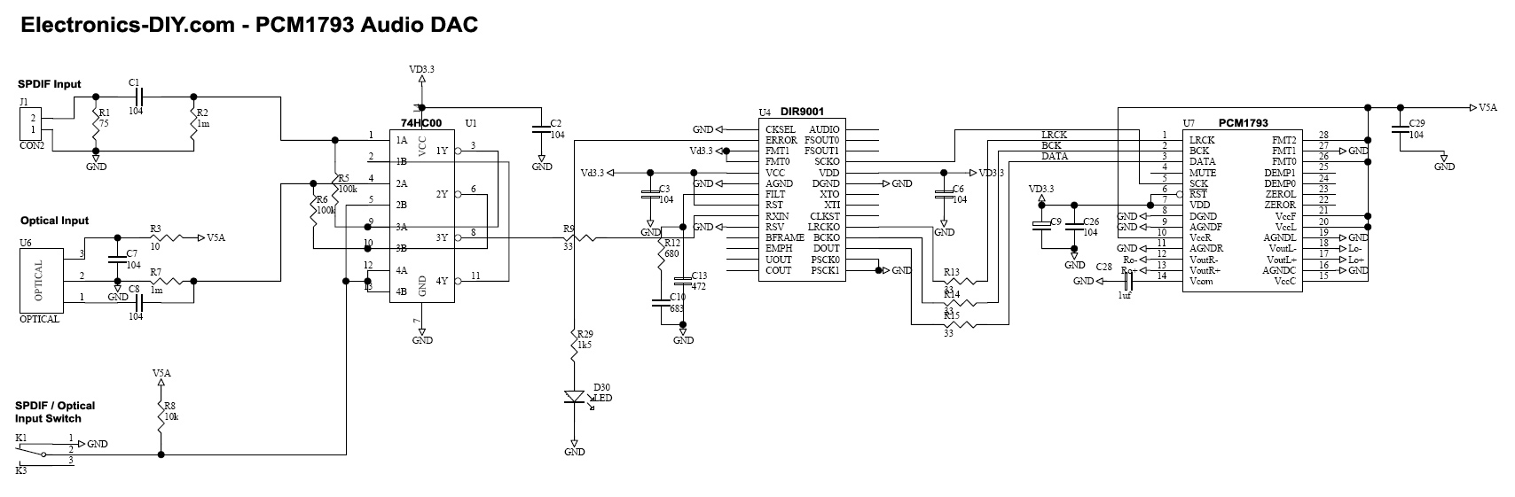
Adjusting the receiver settings in the Digital Audio menu revealed that the default setting was OPTICAL. After changing it to COAX, an improvement in sound quality was noticed. In digital audio systems, the choice between optical (TOSLINK) and coaxial (S/PDIF)...
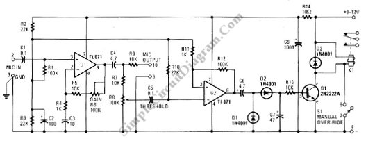
This schematic diagram below shows a circuit of a VOX Box (voice-operated switch). This circuit consists of a Schmitt trigger, a relay driver, and a microphone. The VOX Box circuit operates as a voice-activated switch, utilizing a microphone to detect...
The prototype was successfully assembled on a breadboard and subsequently built on a piece of Radio Shack protoboard for field use. The assembly process took only a couple of hours, and it functioned correctly on the first attempt. This...
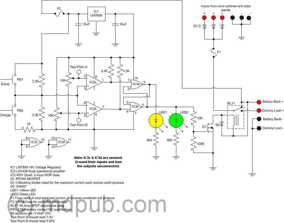
The Over-the-Top type of operational amplifier is ideal for use as a current sensor for battery charger applications. The design described here can be used with chargers for rechargeable batteries (Lead/acid or NiCd, etc.). The 5 V operating supply...
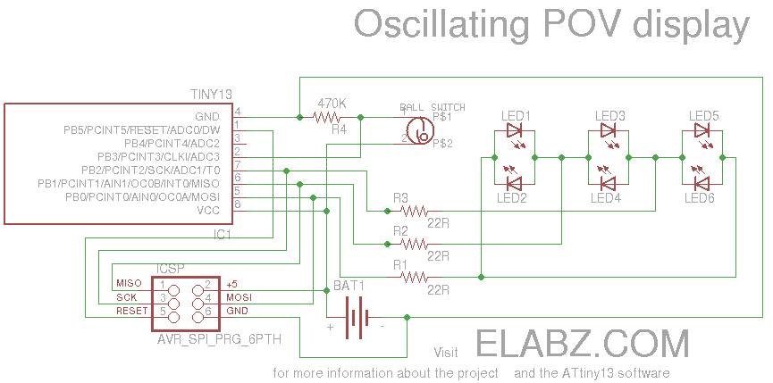
Smart Valentine's Day gift - a movement-sensing box of chocolates with an LED message. Circuit diagram and instructions for building the project using ATtiny13 and Arduino. The project involves creating a movement-sensing box of chocolates that incorporates an LED display...
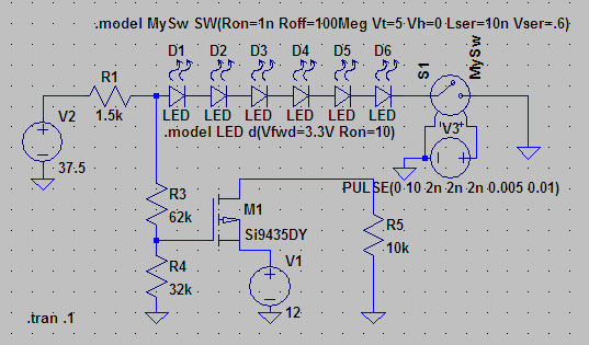
A suitable method to sense when some LEDs in a garage door opener are illuminated. A power source, potentially the same as Vout, connects to a 1.5 kΩ resistor, which then connects to six LEDs followed by a transistor....
Warning: include(partials/cookie-banner.php): Failed to open stream: Permission denied in /var/www/html/nextgr/view-circuit.php on line 713
Warning: include(): Failed opening 'partials/cookie-banner.php' for inclusion (include_path='.:/usr/share/php') in /var/www/html/nextgr/view-circuit.php on line 713