
Sound Sensor

The sound-detecting alarm system utilizes a microphone to capture sound signals, which are then amplified by a high-gain amplifier to ensure that even faint sounds can trigger the alarm. The microphone converts acoustic energy into electrical signals, which are fed into the high-gain amplifier. This amplifier is designed to boost the amplitude of the input signal significantly, providing a stronger output signal that is suitable for further processing.
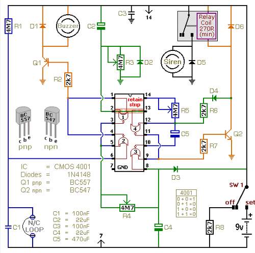
The output from the high-gain amplifier is then sent to a detector-relay driver. This component is responsible for detecting the amplified signals and activating a relay switch when a sound is detected. The relay acts as a control mechanism that can activate various alarm systems, such as sirens or lights, to alert users of the detected sound.
In the case of a latching setup, which allows the alarm to remain activated until manually reset, specific connections must be made to the relay as indicated in the schematic. These connections ensure that once the alarm is triggered by sound detection, it will stay in the activated state until the user intervenes to reset it. This feature is particularly useful in security applications where continuous monitoring is required.
Overall, this sound-detecting alarm system is an effective solution for various applications, including home security, monitoring environments, and alerting individuals to specific sounds or events. Properly implementing the connections and components as outlined in the schematic will ensure reliable operation and responsiveness to sound stimuli. By using a microphone, high-gain amplifier (Fig. 37-10(b)), and detector-relay driver (Fig. 37-10(a)) a sound-detecting alarm system can be constructed. If you want a latching setup, make the dotted connections to the relay shown in Fig. 37-10(a). 🔗 External reference
Related Circuits

A total of 45 pieces of 220-ohm resistors were used to create a 10k-ohm variable resistor. By bending the wire of the resistor, a hook was formed for sewing purposes. For a more compact design than a standard resistor,...

Cuckoo Sound Generator Circuit Schematic. This circuit generates a two-tone effect similar to the cuckoo song. It can be utilized for doorbells or other applications due to a built-in audio amplifier and loudspeaker. The Cuckoo Sound Generator Circuit is designed...

The circuit comprises four main components: a binary counter, a digital-to-analog (D/A) converter, a voltage-controlled oscillator (VCO), and an audio output amplifier. The counting speed of the binary counter is influenced by the frequency output from the VCO, which...
The following circuit illustrates a battery-powered burglar alarm sensor circuit. Features include foil tape and passive infrared sensors (PIRs), as well as magnetic reed contacts. This battery-powered burglar alarm sensor circuit is designed to provide an effective security solution for...
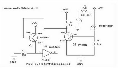
To achieve an optimal voltage swing, the resistance value of R1 must be selected with precision. The sensor resistance, Rsensor, equals a when there is no light exposure and b when light is present. The voltage difference between these...
To compile this software, simply copy and paste it into any current or newer version of the Arduino software. To compile and check for errors, click the play-like button and wait for the software to process. If any errors...