
ir sensors from scratch line follower
To design a sensor circuit that effectively utilizes the potential divider principle, it is essential to consider the relationship between the sensor resistance and the chosen resistor R1. The potential divider configuration allows the voltage output to vary significantly based on the light conditions, which is critical for applications requiring precise light detection.
In this setup, Rsensor will vary between two distinct values: Rsensor = a (high resistance) when no light is detected and Rsensor = b (low resistance) when exposed to light. The output voltage at point 2', derived from the voltage divider formula, can be expressed as:
Vout = (Rsensor / (Rsensor + R1)) * Vin
Where Vin is the input voltage supplied to the divider. When light is present, the lower resistance (b) will yield a higher voltage at point 2', while the higher resistance (a) in darkness will result in a lower voltage.
To optimize the circuit for maximum voltage swing, careful selection of R1 is crucial. It should be chosen to ensure that the output voltage at point 2' demonstrates a significant difference between the two states, allowing for clear differentiation in the ADC readings. This is particularly important in digital applications where accurate light level detection is necessary for proper system functioning.
In summary, the design of this sensor circuit hinges on the proper selection of R1 to maximize the voltage change at point 2' under varying light conditions, ensuring effective performance in applications utilizing ADCs for signal processing.To get a good voltage swing, the value of R1 must be carefully chosen. If Rsensor = a when no light falls on it and Rsensor = b when light falls on it. The difference in the two potentials is: in presence of light and a very large resistance in absence of light. We have used this property of the sensor to form a potential divider. The potential at point 2` is Rsensor / (Rsensor + R1). Again, a good sensor circuit should give maximum change in potential at point 2` for no-light and bright-light conditions. This is especially important if you plan to use an ADC in place of the comparator To get a good voltage swing, the value of R1 must be carefully chosen.
If Rsensor = a when no light falls on it and Rsensor = b when light falls on it. The difference in the two potentials is: 🔗 External reference
Related Circuits

The 60 Watt linear amplifier is a straightforward all-solid-state circuit utilizing the power MOSFET IRF840. The IRF series of power transistors are available in various voltage and power ratings. A single IRF840 can handle a maximum power output of...
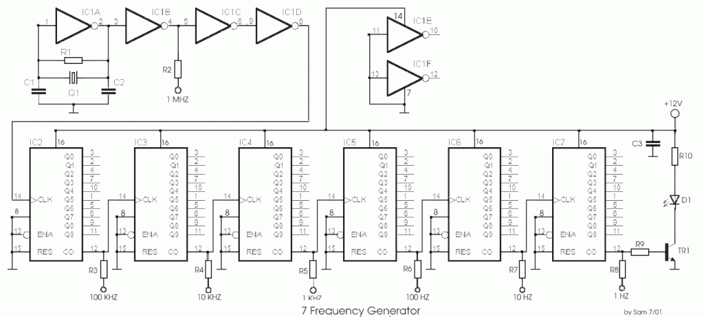
The circuit was designed to create a frequency generator that consists of seven steps during operation. It includes a crystal oscillator, which is an electronic circuit made of... The frequency generator circuit operates through a series of seven distinct steps,...
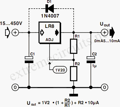
Commonly used 3-pin linear voltage regulators, such as the LM317, cannot handle input voltages exceeding approximately 30V. The LR8A from Supertex Inc is a new adjustable three-pin regulator capable of accepting input voltages up to 450V and supplying an...
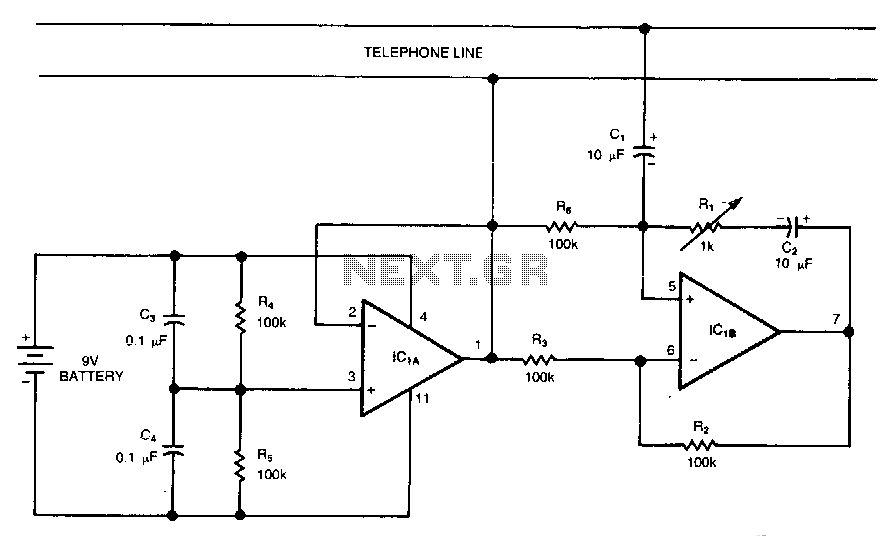
This circuit is a bidirectional amplifier capable of amplifying both signals in a duplex telephone conversation. It operates on the principle of negative resistance. While such an amplifier may be prone to instability, adjusting the load resistor (Rl) can...
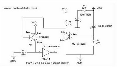
Motion detectors commonly utilize ultrasonic sensors due to their sensitivity and rapid response. However, a significant drawback of these sensors is their tendency to react to environmental vibrations, such as sounds from passing cars or planes, leading to unexpected...
This is a low-cost protection circuit designed to safeguard electrically operated home appliances, such as TVs, DVD players, refrigerators, and other devices, during sudden power outages and the subsequent restoration of mains supply. Appliances like refrigerators and air conditioners...