
Soundbar Design From Start To Finish: Clocks Clocks Clocks
The clock design in digital circuits, particularly in soundbar applications, plays a crucial role in ensuring synchronized operation of various components. A clock signal is essential for timing control, data transfer, and overall system performance. In soundbars, which often integrate multiple digital signal processors (DSPs), audio codecs, and other digital devices, precise clocking is vital for maintaining audio quality and minimizing latency.
The clock circuit typically consists of a crystal oscillator, which generates a stable frequency signal, and may include dividers or phase-locked loops (PLLs) to derive additional clock frequencies required by different components. The choice of the oscillator frequency is determined by the requirements of the digital components in use, ensuring compatibility and optimal performance.
Furthermore, the layout of the clock circuit within the PCB design must be carefully considered to minimize noise and interference. Proper grounding techniques, short trace lengths, and adequate decoupling capacitors are essential to ensure signal integrity. Additionally, the use of differential signaling for clock lines can further enhance performance by reducing electromagnetic interference.
In summary, effective clock design in the digital section of soundbar circuits is fundamental for achieving high-quality audio reproduction and reliable operation of the system.TI`s Dafydd Roche completes his 4-part series on sound-bar design with a detailed explanation of clock design for the digital portion of the circuit 🔗 External reference
Related Circuits
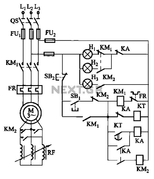
The circuit depicted in Figure 3-165 utilizes a time relay (KT) for controlling the start-up time. Indicator light Hi serves as the power indicator, H2 is designated for the start lights, and H3 functions as the running lights. The circuit...
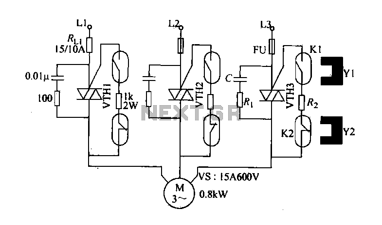
The circuit diagram illustrates a female textile machine power control circuit. VTH1-VTH3 represent TRIACs, while R and C form the absorption line. Rz serves as the triggering current limiting resistor. K1 is designated for starting the reed, and K2...
This power supply is designed for amateur use and has been operational for over 10 years. Its design is straightforward and largely resistant to radio frequency interference (RF). The system incorporates various components, with the most significant being a...
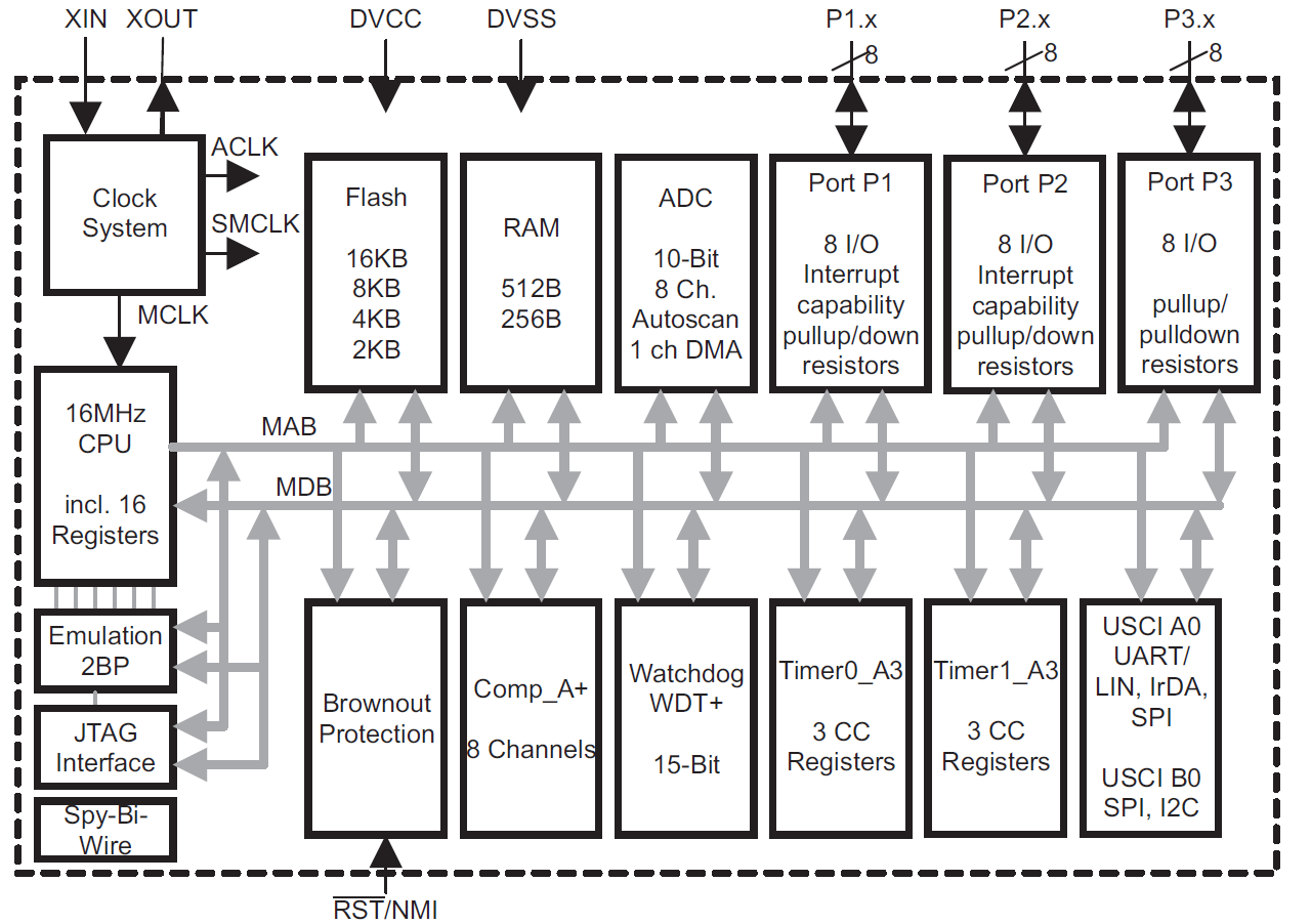
This module provides an overview of the MSP430 microcontroller, instructions on how to read its data sheet, and guidance on selecting the appropriate model for various applications. It is part of a textbook aimed at helping seniors choose Texas...
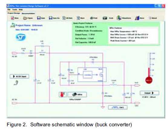
The new VIPer12A and VIPer22A software can be utilized to supply the numerous electronic components needed for home appliances. Various power supply topologies may be employed. The VIPer12A and VIPer22A are integrated circuits designed for power supply applications, particularly suitable...
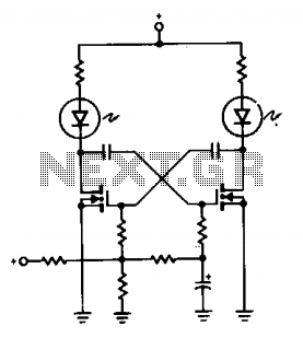
A pair of non-zener MOSPOWER transistors, a pair of LEDs, and a simple RC circuit create an easy sequential flasher with nearly unlimited sequencing time, ranging from momentary flashes to several seconds. The infinite input resistance of the MOSFET...
Warning: include(partials/cookie-banner.php): Failed to open stream: Permission denied in /var/www/html/nextgr/view-circuit.php on line 713
Warning: include(): Failed opening 'partials/cookie-banner.php' for inclusion (include_path='.:/usr/share/php') in /var/www/html/nextgr/view-circuit.php on line 713