
design for amateurs 40A stabilized power supply circuit

The power supply circuit is designed to provide stable and reliable operation for various amateur applications. The inclusion of a 600VA toroidal transformer serves as the primary power source, which is favored for its low electromagnetic interference and efficient performance. The Zener diode establishes a stable reference voltage, which is crucial for maintaining consistent output under varying load conditions.
The resistive voltage divider composed of R5, R6, and VR2 allows for precise voltage regulation, enabling the system to adapt to different input voltages while ensuring that the output remains within the desired range. The Darlington amplifier configuration (Q3) enhances the current gain, ensuring that even small input signals can effectively drive the output stage.
The use of four 2N3771 NPN transistors in the output stage allows for significant power handling capabilities, making this power supply suitable for high-current applications. The direct mounting onto a heat sink without insulation simplifies the thermal management process, as grounding the collectors minimizes the risk of electrical isolation failures.
The current limiting feature (Q1) is an essential safety mechanism, adjustable via VR1, that protects the power supply from excessive current draw, which could lead to overheating or component failure. The overload LED (DL2) provides a visual indication of potential issues, allowing for immediate corrective action.
Short circuit protection is a critical aspect of the design, enabling the power supply to enter a low-power state during a fault condition, thereby preventing damage to both the power supply and connected devices. The recommendation to use an adequately gauged cable is important to ensure that the system can handle high currents without risking damage due to overheating or electrical arcing.
The active rectifier configuration (D1, D2) enhances the efficiency of the power conversion process, ensuring that power loss is minimized during operation. The implementation of a substantial heat sink and mechanical ventilation is vital for maintaining optimal operating temperatures, especially under heavy load conditions, thus prolonging the lifespan and reliability of the power supply.This power supply is designed for amateurs, and has been in operation for over 10 years. Its design is very simple and practically immune to RF. It brings together the individual pieces, is the most expensive part of 600VA toroidal transformer, which can be replaced by another with different characteristics, in the case of a voltage between 17 ~ 2 0V power and right for our needs. Reference voltage of 7. 5 V Zenner diode (6V8 ~ 8V2), shall apply to Q2, which compares the input resistive voltage divider consisting of R5, R6 and VR2, steering Darlington amplifier Q3, which is responsible for driving the output stage, which consists of a driver in Q4 and 4 2N3771 NPN power transistor, which can be mounted directly on the heat sink without insulation, since it is a collector grounded. The source has a current limit (Q1), adjusted by VR1 and overload LED (DL2) and full protection against short circuits, with zero consumption in case of short circuit can be maintained indefinitely in this state without danger.
(Please note that due to the strong power of the power supply with a casual a short length of cable, high or small section that is strong enough to not exceed the maximum current of 40A. Can not be considered a short circuit and cause the supply of a power supply large amounts of energy).
active rectifier (D1, D2) is recommended for a type of cathode metal screw is on the ground, install a heat sink large enough block. As power transistors using a hedgehog as high as possible, without being isolated as above, can be part of the window of an aluminum frame.
We also recommend using mechanical ventilation with the thermostat. 🔗 External reference
Related Circuits
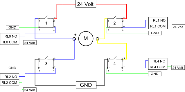
Eight solid-state relays (SSR) and an ADAM-4068 (Serial-I/O device) are utilized to wire a circuit for controlling a motor in a robotic application. The ADAM-6048 is a versatile device that facilitates control of digital inputs and outputs via RS-485...
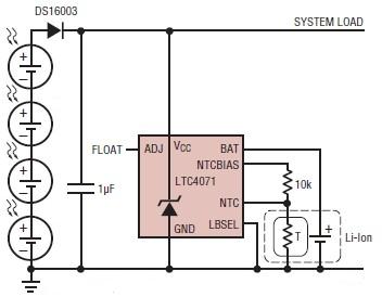
A simple solar-powered battery charger circuit can be designed using the LTC4071 Li-Ion/Polymer Shunt Battery Charger System with Low Battery Disconnect. When VCC reaches the programmed float voltage (4.1V with ADJ floating), the LTC4071 shunts excess current not used...
This power supply is designed as either an auxiliary or a permanent power source for various circuits that require a stabilized DC voltage ranging from 3 to 30V, with a maximum current consumption of 3A. Additionally, this power supply...
The circuit below illustrates generating a single positive pulse which is delayed relative to the trigger input time. The circuit is similar to the one above but employs two stages so that both the pulse width and delay can...

This circuit is an active filter designed for subwoofers, featuring a 24 dB per octave Bessel filter with a cutoff frequency of 200 Hz. It is suitable for those interested in experimenting with audio circuits in the subwoofer frequency...
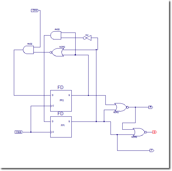
In this lab, flip-flops will be utilized. Xilinx provides a comprehensive library of sequential circuits, which is recommended for circuit searches: Xilinx Reference Library. The objective of this lab is to implement a sequential circuit that controls three LEDs:...