
XQP frequency sensitive start-type control box circuit
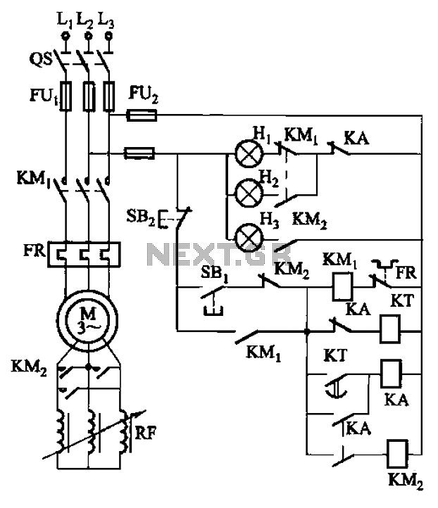
The circuit operates by employing a time relay (KT) that initiates the start-up sequence after a predetermined delay. This relay is crucial in managing the timing aspect of the circuit, ensuring that the system does not engage immediately upon power-up, which can help prevent potential damage or operational issues.
The power indicator light (Hi) provides a visual cue that the circuit is energized. This is essential for operators to confirm that the system is receiving power. The start lights (H2) illuminate to indicate that the system is in the process of starting up. This feature is particularly useful in applications where the start-up sequence may take some time, allowing users to monitor the status of the system easily.
Once the system has successfully started, the running lights (H3) activate, signaling that the circuit is operating as intended. This sequential lighting system not only enhances user awareness but also improves safety by clearly indicating the operational status of the equipment.
The overall design of this circuit ensures that each component plays a critical role in the functionality and user interaction with the system, providing a reliable and efficient operation. Proper attention to the timing relay's specifications and the indicator light ratings will further enhance the performance and longevity of the circuit. Circuit shown in Figure 3-165. Start-up time by the time relay KT control. Figure, Hi is the power indicator, H2 for the start lights, H3 for the running lights.
Related Circuits

This linear amplifier provides a 10-W PEP output with a 1.25-W drive on the 10 m band. The transformers, T1, T2, and T3, consist of 10 turns of bifilar windings on an FT-50-43 toroidal core and are designed for...
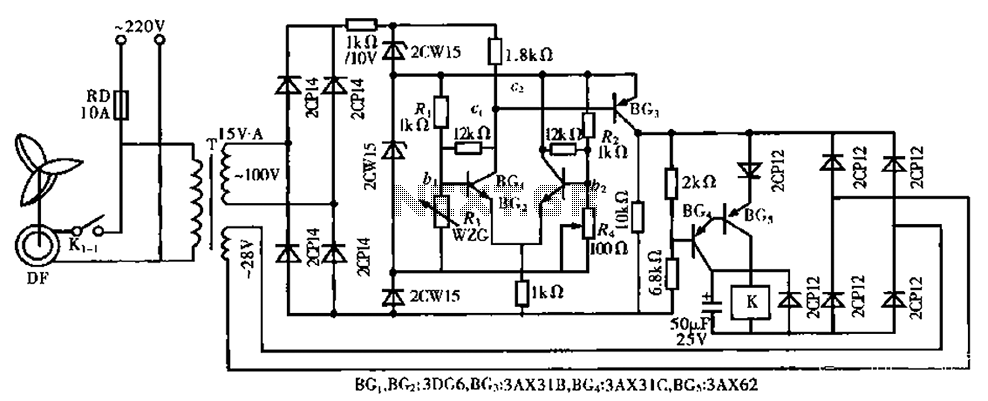
The circuit is a bistable circuit where each bistable unit is controlled by high and low output levels. When power is supplied to the circuit, current flows through components R13, CL, and VD to VD2 for full-wave rectification. The...
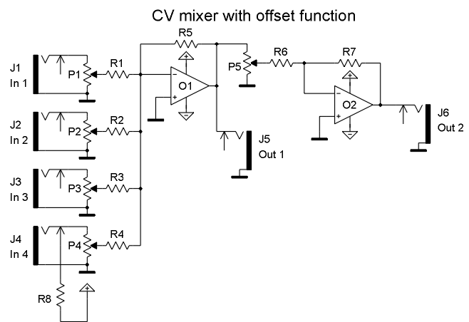
Input J4 features an offset function that is activated only when no plug is inserted into J4, as the switching contact of J4 connects to the positive supply voltage through the protection resistor R8. The inverting sum of all...
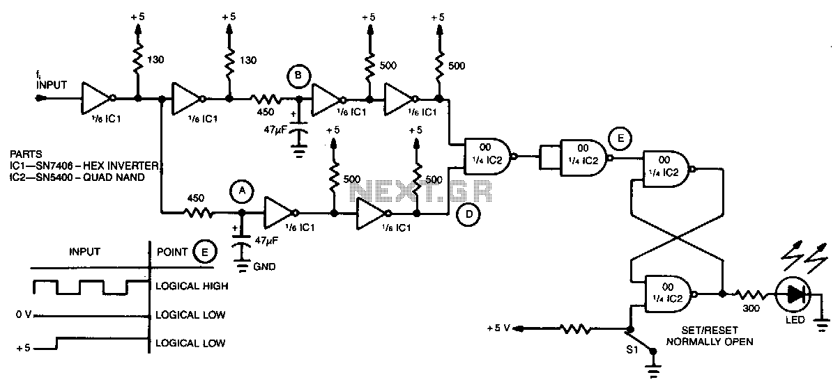
A simple inverter and NAND gate can be connected to create a highly compact and reliable digital frequency detector. This circuit is capable of detecting frequencies up to 3 MHz with a 50% duty cycle. When a frequency appears...
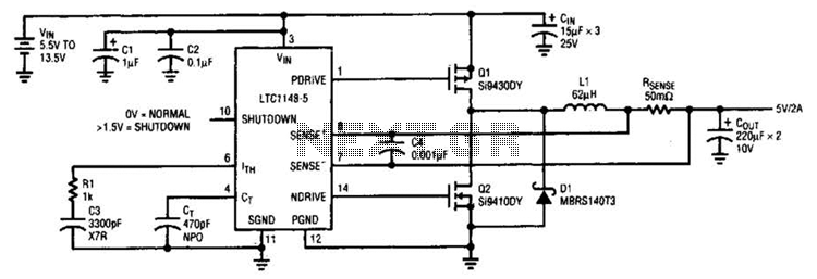
A typical LTC 1148 surface-mount application provides 5 V at 2 A from an input voltage range of 5.5 V to 13.5 V. The operating efficiency, illustrated in B, peaks at 97% and remains above 90% from 10 mA...
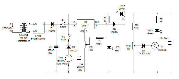
Battery charger utilizing solar and electrical power with a circuit diagram. This dual power source battery charger can charge a lead-acid battery using two different power sources. The battery charger circuit is designed to efficiently charge a lead-acid battery by...
Warning: include(partials/cookie-banner.php): Failed to open stream: Permission denied in /var/www/html/nextgr/view-circuit.php on line 713
Warning: include(): Failed opening 'partials/cookie-banner.php' for inclusion (include_path='.:/usr/share/php') in /var/www/html/nextgr/view-circuit.php on line 713