
Source suspended programmable instrumentation amplifier PGA203

The PGA203 is a precision instrumentation amplifier designed for applications requiring high accuracy and low noise. It operates with a wide supply voltage range and offers programmable gain settings, making it suitable for various signal conditioning tasks. The twisted pair inputs help in minimizing noise and interference, which is critical in sensitive measurement applications.
In this configuration, the 1M resistor connected to the input pins plays a vital role in setting the input bias current. This bias current is essential for the proper functioning of the amplifier, ensuring that it operates within its optimal range. The choice of a 1M resistor balances the need for sufficient bias current while minimizing the impact on the input signal.
The output of the PGA203 can be further processed or fed into an analog-to-digital converter (ADC) for digital signal processing. Proper decoupling capacitors should be placed near the power supply pins of the PGA203 to filter out any noise from the power supply, enhancing the overall performance of the circuit.
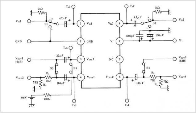
Overall, this schematic effectively illustrates the use of the PGA203 in amplifying low-level signals with high precision, making it a valuable component in instrumentation and measurement systems. As shown in FIG source constituted by PGA203 programmable instrumentation amplifier suspended. Because the input signal is applied to PCA203 twisted pair inputs, so in suspensi on, after the PGA203 amplifies the output signal. Here we should note that in PGA203 input feet to a 1M resistor to provide channel amplifier input bias current.
Related Circuits
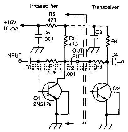
This simple, inexpensive, wideband RF amplifier provides 14 dB gain on two meters without the use of tuned circuits. The RF amplifier described operates within the two-meter band, which typically spans frequencies from 144 to 148 MHz. It is designed...
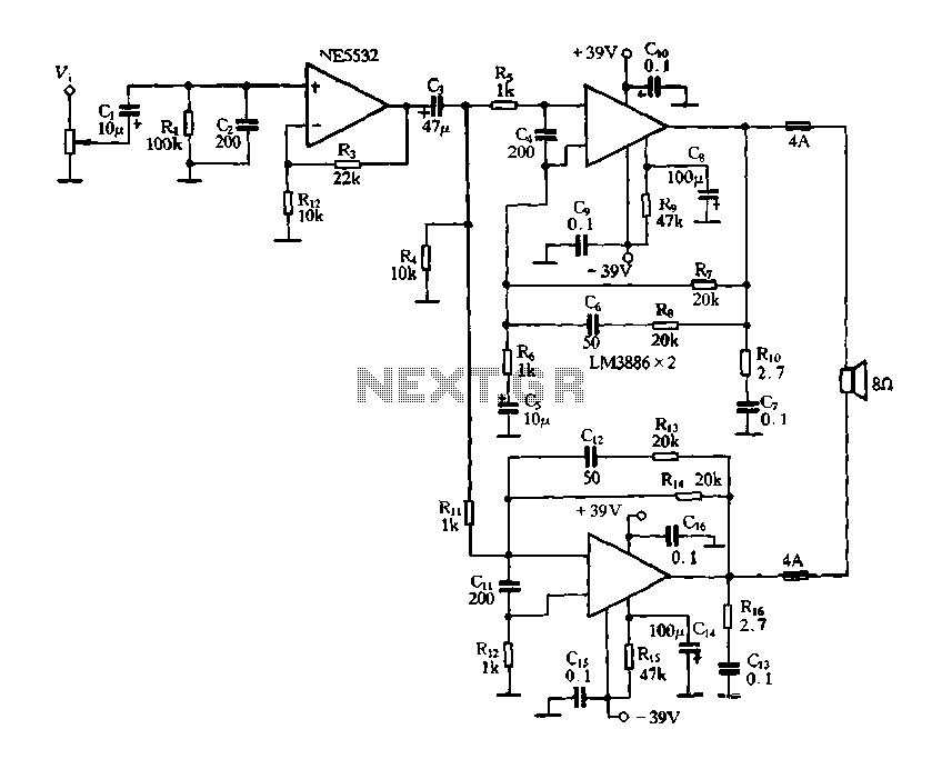
Figure 2-60 depicts a practical circuit for the LM3886 amplifier, which incorporates an NE5532 as a preamplifier, capable of delivering an output power of up to 200 Watts. Given the high output power of the LM3886 power amplifier, it...

This circuit exhibits an exceptionally fast high-frequency response, as demonstrated by applying a 100 kHz square wave to the input. All graphs were produced using Tina Pro. The circuit's design is optimized for high-frequency applications, showcasing rapid response times that...
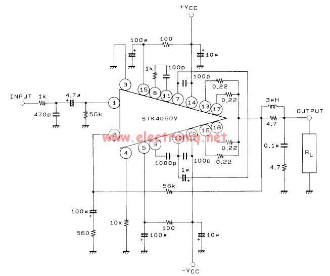
This 200-watt audio amplifier circuit diagram is based on the STK4050V high-power audio amplifier IC, designed to deliver up to 200 watts of audio power on a single channel. The STK4050V 200-watt audio amplifier circuit is pin-compatible with other...
The circuit is designed to deliver approximately 10% distortion on a 4 Ohm to 8 Ohm loudspeaker. The LM4756 amplifier can output 7W of power. Utilizing four pairs of 2SC5200 and 2SA1943 transistors, this configuration can generate around 500W....
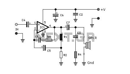
NJM2274AR is a sub-package of NJM2274A. For a detailed description, please refer to NJM2274A. The datasheet for NJM2274AR can be downloaded from the link below. Manufactured by New Japan Radio Co., Ltd. The NJM2274AR is a component that serves as...