
Hi-Fi Preamplifier Circuit Project

The circuit's design is optimized for high-frequency applications, showcasing rapid response times that are crucial in various electronic systems. The application of a 100 kHz square wave serves as a benchmark for evaluating the circuit's performance, allowing for the analysis of its transient response characteristics.
In this setup, the circuit likely includes components such as operational amplifiers, transistors, or specialized high-speed ICs that are capable of handling the rapid changes in voltage associated with a square wave input. The frequency response can be assessed through the output waveforms, which should ideally reflect minimal distortion and a swift transition between high and low states.
The use of Tina Pro for graph generation indicates a reliance on simulation tools to validate the circuit's performance before physical implementation. Tina Pro enables the visualization of waveforms, allowing for the examination of parameters such as rise time, fall time, and overshoot, which are critical for ensuring that the circuit meets the required specifications for high-speed operation.
In summary, the circuit's ability to maintain a fast response to a 100 kHz square wave input is indicative of its suitability for high-frequency applications, and the simulation results serve as a valuable resource for further refinement and testing.This circuit has an exceptionally fast high frequency response, as demonstrated by applying an 100kHz square wave to the input. All graphs were produced using Tina Pro. 🔗 External reference
Related Circuits
This circuit is designed to indicate, via a flashing LED, when room noise exceeds a predetermined threshold, selectable from three fixed levels: 50 dB, 70 dB, and 85 dB. The circuit utilizes two operational amplifiers to amplify the sound...
The noise reduction circuit is designed to minimize disturbances that occur during pauses in music playback. It functions by attenuating the signal output during these intervals. The noise reduction circuit operates on the principle of detecting silence or low audio...

This circuit diagram of a digital clock utilizes six common anode seven-segment displays to indicate the time. It does not require microcontrollers or PICs for operation. The circuit operates using the MM5314 integrated circuit, functioning at either 50 Hz...
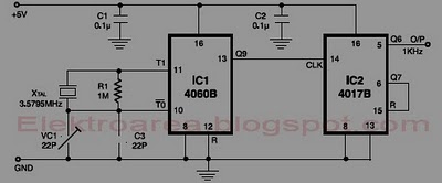
This circuit is designed for accurate time-base generation utilizing the commonly available 3.5795 MHz crystal, which is frequently used in telecommunication equipment. A crystal-based oscillator combined with a divider IC chain or a similar circuit, such as an ASIC,...
The thermistor utilized has a resistance of 15k ohms at 25 degrees Celsius and 45k ohms at 0 degrees Celsius. A suitable bead-type thermistor can be sourced from the Maplin catalogue. The inclusion of a 100k potentiometer enables this...
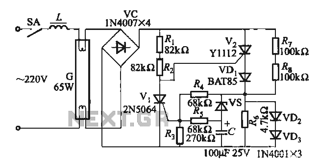
One electronic ballast circuit is depicted in Figure 2-11. This circuit utilizes a specialized fluorescent lamp starter thyristor, SCR Y1112, which is superior to ordinary thyristors due to its ability to maintain a higher current value and dU/dt values....