
Spark-Gap Tesla Transformer

Testing was performed using two different primary capacitors. The first was a water-filled jar capacitor made from aluminum foil, which measured 352 pF with an estimated voltage rating of approximately 20 kV. Various tests were conducted by adjusting the supply voltage, modifying the spark gap configuration, and changing the discharge terminals. A series spark gap arrangement involving four or more gaps yielded the best performance.
The total gap spacing should not exceed 5-6 mm to protect the primary capacitor, and a series configuration was found to be quieter. The streamers produced at the discharge terminal were clearly visible in low-light conditions, with a measured spark discharge of approximately 3-3.5 cm using a grounded rod, resulting in an estimated output voltage of around 70 kV. The coils and streamers were documented in accompanying figures.
Subsequently, the same secondary coil was tested with a 2.53 nF, 16 kV MMKP capacitor array, necessitating a replacement of the primary inductor due to the increased capacitance. This adjustment required a significantly lower primary inductance. The spark length achieved was about 4.5-5 cm; however, the firing rate of the spark gap decreased. A higher current output from the high-voltage transformer was needed to maintain performance.
The construction and testing of these coils highlight the importance of careful selection and configuration of components in high-voltage applications, particularly in achieving optimal spark discharge characteristics and ensuring the safety and efficiency of the system. The interaction between capacitance, inductance, and spark gap design plays a crucial role in the overall performance of the circuit.I built two secondary coils: Small coil D25.4/H119 (Diameter=25.4mm and Height=119mm) and Medium coil D73/H228. I experimented with the spark gap, and observed that a series spark gap is better in terms of power handling, noise, and spark discharge length.
The capacitance is very important. It should be able to pump a high current, so a low ESR and a low inductance pulse type capacitor is required.
I tested this coil with two different primary caps. First I constructed a water filled jar cap using aluminum foil as shown in Fig. 3, and measured its capacitance as 352pF. The estimated voltage rating was about 20KV. I run a
bunch of tests by varying the supply voltage, changing the spark gap configuration, and putting different discharge terminals. A series spark-gap configuration involving four or more gaps gives the best performance.
However, the total gap spacing must not be larger than 5-6mm to protect the primary capacitor.
A series arrangement is quieter. The streamers emanating from the discharge terminal are quite visible in the dark. And I measured a spark discharge of about 3-3.5cm using a grounded rod. The estimated voltage output was about 70KV. The coil and the streamers are shown in Fig. 2 and 3, respectively.
Then I tested the same secondary using a 2.53nF/16KV MMKP array as shown. Primary inductor was replaced too. Since the cap has been increased, a much lower primary inductance was needed. The spark length was about 4.5-5 cm. However, the spark gap firing rate has been reduced. A higher current is needed from the HV transformer.. By 4beowulf7 - [email protected]
Related Circuits
A battery-operated Tesla coil is being developed, and assistance is needed for converting direct current (DC) to alternating current (AC) to power a high-voltage transformer. To convert DC to AC for powering a high-voltage transformer in a Tesla coil circuit,...
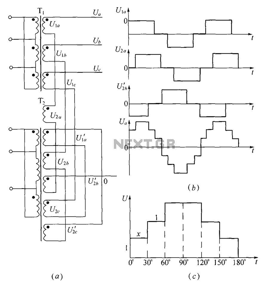
As shown, (a) for the three-phase step wave inverter output transformer winding connections; (b) in the figure, its output waveform. The three-phase step wave inverter is designed to convert direct current (DC) into a three-phase alternating current (AC) output. This...
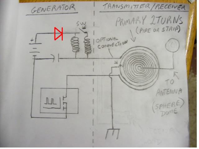
At approximately 50 kHz, a voltage exceeding 40 volts is observed at the receiver. LEDs illuminate without issues, although a 5mm LED was damaged. A capacitor connected to the AC was obstructing energy transfer. The primary negative was connected...
This circuit is designed to demonstrate high frequency and high voltage, capable of producing up to approximately 30 kV, depending on the transformer utilized. It is an economical and straightforward project, primarily using a standard TV flyback transformer. The...
This circuit is straightforward. The accompanying graphics and images provide all necessary details. After gathering all materials, connect the transistor according to the provided schematic. The circuit in question is a basic transistor circuit that serves as an introductory project...
If you want to build one yourself, you have to get two audio transformers which have 1:1 transformation ratio and greater than 1 kohm impedance. There are high quality audio transformers in the markets that meet those specs, but...