
Circuit Diagram for a 12V LED Lamp

LED specifications include direct voltage (Vf), maximum current consumption (If), and approximate resistance (R = Vf/If). The power rating is also provided in the datasheet. It is important to avoid exceeding the reverse voltage (Vr) and to identify the correct polarity when connecting the LED. LEDs can be connected in parallel or series; in parallel, currents are summed, while in series, voltages are summed.
LEDs typically require a current-limiting resistor in most applications to ensure longevity and reliability. Without proper current limiting, the margin between non-operation and burnout can be dangerously small. Proper design practices suggest always using resistors in series with LEDs to prevent damage and ensure consistent performance.
For those interested in using LEDs, it is recommended to consult manufacturer datasheets for specific current ratings and other parameters. Some manufacturers offer LEDs with built-in resistors for specific voltage applications, simplifying the design process.
In conclusion, while there are various methods to use LEDs, adhering to established design principles and understanding the electrical characteristics of LEDs is essential for creating reliable and efficient circuits.What color LED it makes a difference. One LED or how many 3mm 5mm What is you power source These are vital things to answer. More info required. It does not compute! There`s them that knows and them that just thinks they know, whitch are you Stir the pot and see what rises up. I have catalytic properties I get a reaction going. Here you go, one very basic electrical diaghram for a LED. The resistor will depend on the particular LED used and the desired light intensity from say LED. As a fellow member stated, you can use Ohms law to determine the value of the resistor. that is you take the supply voltage subtract the LED`s forward voltage (this is where the color comes in) then decide on the current to be used and then select then the resister. V=IxR I=V/R R=V/I. That sums it up. There`s them that knows and them that just thinks they know, whitch are you Stir the pot and see what rises up.
I have catalytic properties I get a reaction going. Let`s assume that each LED`s forward voltage drop is 1. 2Vdc (makes it easier for me). This means that if I string ten LEDs in series, I won`t need a resistor since 10 x 1. 2vdc = 12vdc. If your LEDs are 1. 5Vdc, you`ll need eight in series and no resistor. If they are, say, 2. 1Vdc, it`s going to be a bit different. 6 x 2. 1vdc = 12. 6Vdc, which is a little more than your supply. It might still work albeit a little dimmer. If you use five, 5 x 2. 1Vdc = 10. 5Vdc. That means your resistor will have to drop 1. 5Vdc. You`ll need to know the forward current of your LEDs in order to calculate your resistor`s value. Now take out your calculator and start pushing buttons. Si tienes el cG³digo del LED, ve sus valores de consumo, voltaje directo "Vf(Vdc)", mG ximo consumo de corriente "If(mA)", la resistencia aproximadamente del LED serG (R=Vf/If), la potencia tambiG©n esta en el manual, Pd(mW) = [P=VfxIf] (aprox), como te habrG s dado cuenta la formula es lineal, si tu LED es de 12 Voltios DC no requieres ninguna resistencia si tu fuente es de 12 voltios, la resistencia propia del LED actG a como limitador de corriente, solo ten cuidado de no ponerlo al revG©s no puede exceder el Voltaje Reverso "Vr", que tambiG©n esta en el detalle tG©cnico, identifica bien el G nodo y el cG todo, el LED es un diodo emisor de luz y como diodo lo puedes identificar con un multitester. Si tienes mas de un LED puedes colocarlos de forma paralela o seriales, si son (paralelas: suma las corrientes), si son (seriales: suma los voltajes), por cada LED.
Vulcan, do you actually use LED`s in the way you describe I have used LED`s for 30 years and never heard such a recommendation. Just out of curiosity I checked a couple with a current limited supply and as expected the voltage difference between really dim and over current is only a couple of tenths of a volt.
It just defies all recommendations I have ever read in LED data sheets and in order to assure that my designs had a margin of safety for the parts I have never attempted to use LED`s without resistors (excepting special pulsed applications which are beyond the scope of this application). What kind of designs have you done where you used LED`s in this manner I was a lot younger then and I naively thought I could build a lamp out of LEDs (red ones at that but it was experimental).
I stringed 8 LEDs in series, put a 12Vdc power source across it and it worked! But the light intensity was dismal. I haven`t tried it since (about 25 years ago) but I think the same principle applies. I guess the advantage I had back then was that I never read that document you mentioned about the proper application of LEDs. Would the thing have lasted I didn`t try. The LEDs weren`t hot but, after seeing the result, I reused the parts for other projects. I am, however, willing to try it again using the super-bright LEDs now available. Well I just used a 2000mcd super bright LED that I bought about a month ago for a project and it measured a much smaller difference between the very dim (1.
65v) point and the too much current (1. 9v) point of operation than an older LED from 30 years ago. That would indicate that the no current limit method is even less appropriate than it might have been with older LED`s. I could never let a design go out where the margin between doesn`t work and burns out is only a couple of hundred millivolts and I didn`t just try something once years ago I have used LED`s in over 40 successful designs.
I`m going to have to stick by my contention that this is a very bad way to attempt to use LED`s and one I have never seen used in hundreds of good designs. Good luck to anyone who may attempt to go that route. I would seriously recommend that you don`t and that you seek other design application recommendations from the manufacturers if you don`t believe me.
That`s okay. We agree to disagree. In the interest of "proper" design, however, you`re right. Better to build it to last than to build it in minimalist fashion. For your info, I`ve also built circuits in the succeeding years and I`ve always had to put resistors in series with single LEDs. It`s just that I`ve never had reason to put a whole bunch of them together like I did before (I used LEDs for indication, not illumination).
This post has made me curious. I`ve got an LED flashlight here and I`m tempted to open it up. `Been with me for two years and it`s still as bright as the day I bought it. It`s got eight LEDs and two AA batteries. I don`t think it`s series connected though. Maybe parallel. `Let you know later. Estas en lo correcto Vulcan, tu formula del calculo de la Resistencia en funciG³n al voltaje, pero la pregunta no especifica si tiene una fuente de voltaje de 12 voltios o esta usando un LED de 12 voltios. - Los voltajes de LED comunes estG n entre (1. 65 a 2. 60 Vdc) "los comerciales", con corrientes de (35 a 50 mA), segG n aplicaciG³n y color. - Lo que nos esta pidiendo es un diagrama que creo que ya cumplimos. Usted tiene razG³n. G‰l no dijo que el suministro de energGa era 12V o si esto fuera el LED que era 12V. Kingbright vende LEDs con resistencias incorporadas, sG³lo descubrG. Dos modelos que vi eran para 5V y el otro para 12V. You`re right. He didn`t say that the power supply was 12V or if it was the LED that was 12V. Kingbright sells LEDs with built-in resistors, I just discovered. Two models I saw were for 5V and another for 12V. LED need 0. 7V to turn on. After that most of them should have MAX current of 20mA. Some high output one would use higher current, they usually come with heatsink. Read manufacturer datasheet for max current rating for your LEDs. The easiest way to find out max current/brightness is try. Using a variable voltage source and amp/volt meter, connect LED to source. Increase voltage from 0 till LED turn on. Keep increasing and note 🔗 External reference
Related Circuits
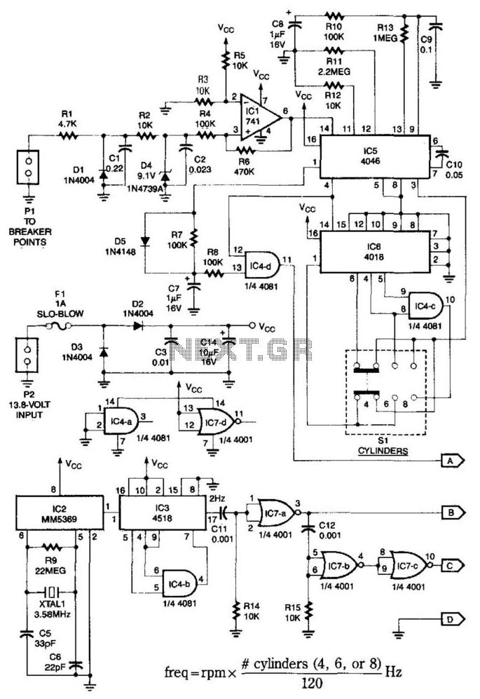
This system is compatible with 4-, 6-, or 8-cylinder automobiles. The timebase generated by IC5 functions as an oscillator that drives counter IC6, which divides the frequency by 6, 4, or 3 for 4-, 6-, or 8-cylinder engines, respectively....
This is a design for a flashlight that two 220 V alternating lights can control. The flashlight uses only one IC. IC1a IC1c to be used for the flashing signal generation. The output of IC1c thyristor T1 is controlled,...
The basic circuit illuminates up to ten LEDs in sequence, following the rhythm of music or speech picked up by a small microphone. The expanded version can drive up to ten strips, formed by up to five LEDs each,...
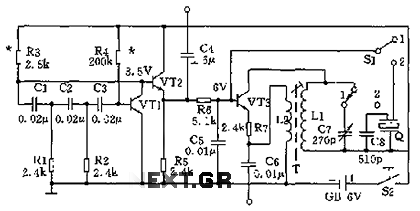
The high-frequency signal generator is designed to produce a low frequency of 1 kHz, an intermediate frequency (IF) signal of 465 kHz, and high frequencies ranging from 525 kHz to 1605 kHz. This device is particularly useful for radio...
A 12V to 3V converter. This is a simple and inexpensive circuit designed to convert voltage from 12V to 3V. In fact, this is a basic regulator circuit. This 12V to 3V converter circuit typically employs a linear voltage regulator,...
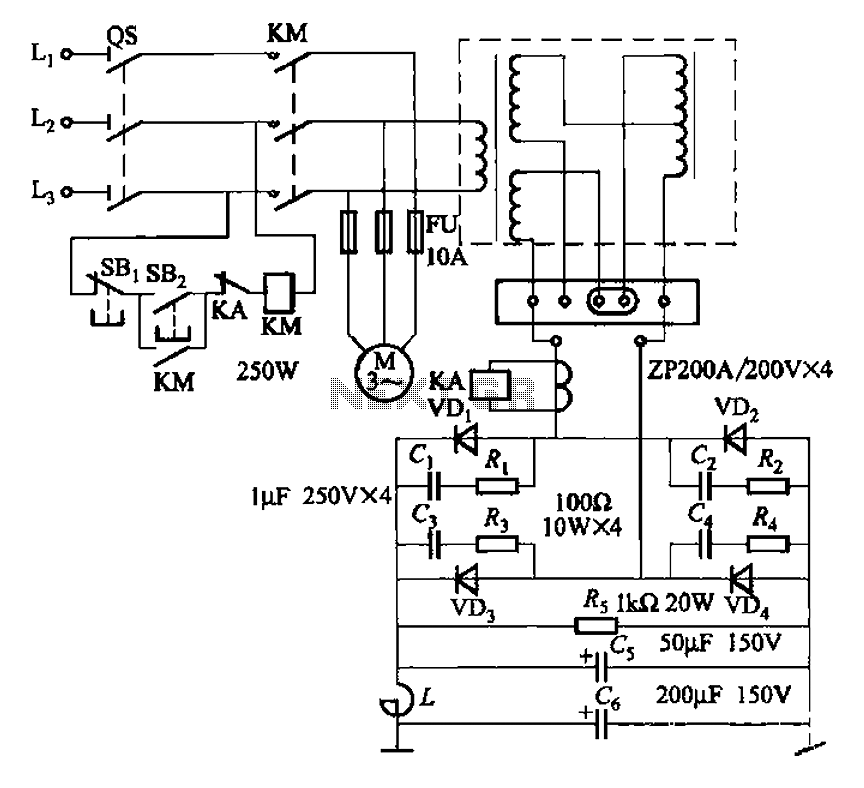
After restructuring the AC and DC arc welding machine circuit on the BX series AC arc welder by installing a rectifier device, it can be converted into an AC and DC arc welding machine. This restructuring results in a...