
Speaker protector

The described circuit utilizes a time delay mechanism to protect the speaker from damaging transients that occur when the amplifier is initially powered. The inclusion of a bridge rectifier (D1) allows for the conversion of AC voltage from the amplifier’s power supply into DC, which is then filtered by capacitor C1 to provide a stable voltage for the subsequent components. The Darlington pair configuration (Q1 and Q2) serves as a current amplifier, ensuring that the control voltage for the relay is sufficient to activate it only after the desired delay.
The resistor R1 is critical in determining the charging time of capacitor C2, which directly correlates to the delay before the relay engages. The selection of C2 and R1 values is essential; for a delay of approximately 2 seconds, typical values might be in the range of a few microfarads for C2 and several kilo-ohms for R1, but these should be calculated based on the specific circuit requirements and the supply voltage level.
Once the relay is activated, it connects the speaker to the amplifier output via the N/O contact, allowing audio signals to pass through. Meanwhile, the N/C contact of the relay, which is connected to resistor R2, grounds the amplifier output during the delay period. This grounding prevents any DC voltage from reaching the speaker, thereby protecting it from potential damage.
Overall, this circuit design effectively mitigates the risk of speaker damage due to high voltage transients by ensuring a controlled connection to the audio output of the amplifier, enhancing the longevity and reliability of the speaker system.When the amplifier is switched on, the speaker gets popped up by a high voltage and you can hear a loud thud sound from the speaker. This stuff is very harmful to the speaker and it drastically reduces the speaker`s life. The circuit shown here connects the speaker to the power amplifier output only after a few seconds the amplifier is powered ON.
A simple transistor based time delay circuit is used for attaining the purpose. The circuit is so connected to the existing amplifier that, when the amplifier is powered on the bridge D1 also gets powered through the amplifier`s power switch. Capacitor C1 filters the output of bridge rectifier D1. When the power switch is made ON, the Darlington pair (Q1 and Q2) gets switched ON only after the capacitor C2 is sufficiently charged (to 0.
7V) through the resistor R1. Here the value of C2 and R1 are so selected that the time delay is around 2 seconds. So the relay gets activated only after a few seconds the amplifier is powered ON and until that time the speaker will be kept isolated from the amplifier`s audio output as the speaker is connected to the amplifier`s output through the N/O contact of the relay. During this initial delay period the output of amplifier will be grounded by the resistor R2 through the N/C contact of the relay.
This is done in order to ensure that the DC blocking capacitor at the amplifier`s output is charged before it is connected to the speaker. 🔗 External reference
Related Circuits
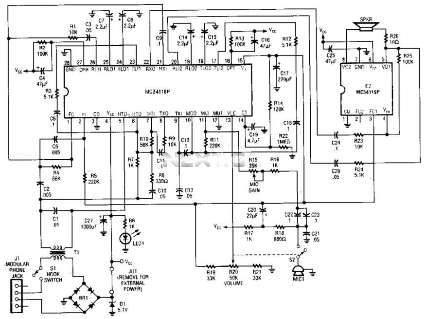
Using a Motorola MC34118 speakerphone IC, this adapter can be utilized with a standard telephone to enable speaker functionality. The device is powered from the phone line; however, it can also be powered through an external power supply if...

The simplest example of a Switch Mode Power Supply (SMPS) utilizes three transistors (C3807, A1015, and power transistors). A common issue that arises is related to the feedback circuit, which can lead to an output voltage (B+) that exceeds...
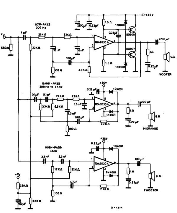
A simple multiway active speaker audio system can be designed using the TDA2030 audio IC. This TDA2030 active speaker audio system circuit is created to deliver optimal acoustic performance, as each loudspeaker is specifically designed and optimized for a...
An LED will fail if the current flowing through it is excessively high. This issue can be easily resolved by incorporating a simple resistor in series, which is an effective and low-cost solution. However, as the power supply voltage...
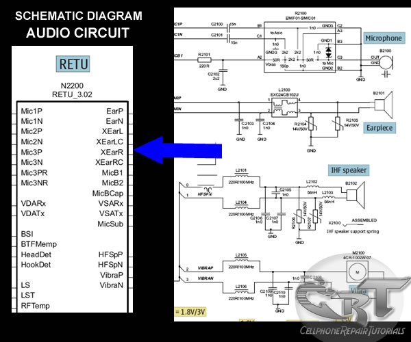
A mobile phone's microphone or mouthpiece is a component that converts sound signals into electrical signals. The earpiece speaker converts electrical signals back into sound signals, and similarly, the IHF, buzzer, or ringer speaker performs this function as well....
In a stereo system, it is often important to determine whether the speakers are polarized. This can be especially problematic if the speaker cables lack polarity markings. The circuit described will assist in identifying the correct terminals for the...