
Understanding Mouthpiece or Microphone Earpiece and IHF or Buzzer Speakers Circuit on mobile phones
The microphone in a mobile phone operates by converting acoustic energy into electrical energy through a diaphragm that vibrates in response to sound waves. This electrical signal is then processed by the audio codec, which encodes and decodes audio signals for transmission and reception. The earpiece speaker, functioning in the opposite manner, receives electrical signals from the audio codec and converts them back into sound waves for the user to hear.
In modern designs, the inclusion of an EMI filter is crucial for maintaining audio quality by minimizing electromagnetic interference, which can introduce noise and distort the audio signal. The EMI filter typically consists of inductors and capacitors that work together to suppress unwanted high-frequency noise while allowing the desired audio frequencies to pass through.
The microphone signal is characterized by its dual polarity, where the positive and negative phases are essential for proper signal integrity. After passing through the EMI filter, the signal is further conditioned by capacitors that block any DC offset, ensuring that only the AC audio signal is processed further by the audio codec.
The vibrator motor, while not a traditional audio component, plays a significant role in enhancing the user experience by providing haptic feedback. This feedback is generated through mechanical vibrations, which can be felt by the user, thus adding a tactile dimension to notifications or alerts.
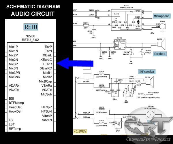
The printed circuit board (PCB) layout is crucial for the effective integration of these components. The microphone, earpiece, IHF speakers, and vibrator motor are interconnected but spaced apart to prevent interference. All connections lead to the audio codec, which serves as the central processing unit for audio signals in the mobile device. Proper routing and separation of these signals on the PCB are essential for minimizing crosstalk and ensuring optimal performance of the audio subsystem.A mobile phones microphone or mouthpiece is a component used to convert sound signal into an electrical signal. The earpiece speaker is the one that converts electrical signal into a sound signal, likewise also the IHF, buzzer or ringer speaker do.
A typical and modern designed of mouthpiece circuit is being protected by an EMI- Filter to prevent sound interruption, before it then feeds the audio signal to the audio codec circuit. Some microphone circuit other mobile phones have no EMI Filter like the one showed below. The microphone line signal is being presented into positive and negative polarity, and those two polarity lines is being filtered again by two capacitor after being pass by from an EMI-Filter, in order to remove the DC (direct current) coming from the EMI-filter. A vibrator motor although this is not a sound converting device but it generates a vibration which generates sounds, this one is also included in audio circuitry.
Here`s an example mapping layout of a Microphone, Earpiece, IHF speakers and Vibrator motor connections on a mobile phones printed circuit board. Each connection were both separated and apart from each other but all of each line is being pointed towards in audio codec circuit.
🔗 External reference
Related Circuits
The receiver circuit and display module will receive the high-frequency AC power cord and decode it to provide actual temperature readings using digital IC No. CD4553 (Three-digit BCD Counter IC) and IC CD4511 (BCD-to-7-Segment Latch/Decoder/Driver IC). The frequency pulses...
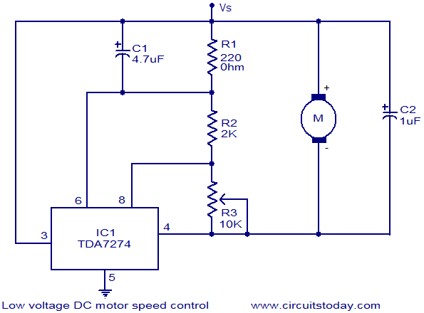
The circuit diagram illustrates a low voltage/low power DC motor speed controller utilizing the TDA 7274 integrated circuit from ST Microelectronics. The TDA 7274 is designed for low voltage and low power applications, featuring an internal voltage reference, a...
Electrical equipment provided for a power supply circuit design in the power section, as illustrated below. The power supply circuit design is a critical component in various electronic systems, serving as the backbone for powering other devices. The schematic typically...
This audio processor circuit features the SSM2045 integrated circuit (IC), designed specifically for electronic music applications, along with the 741 operational amplifier (op-amp) IC. The circuit is configured as a low-pass filter with a DC voltage control for gain....
There is no PCB since there are no components to mount on one. The object was to create a source of ultraviolet light as fast as possible. The UV tubes I bought from a lighting shop for use with...
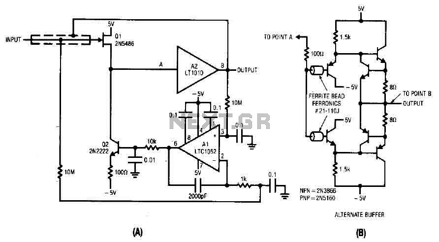
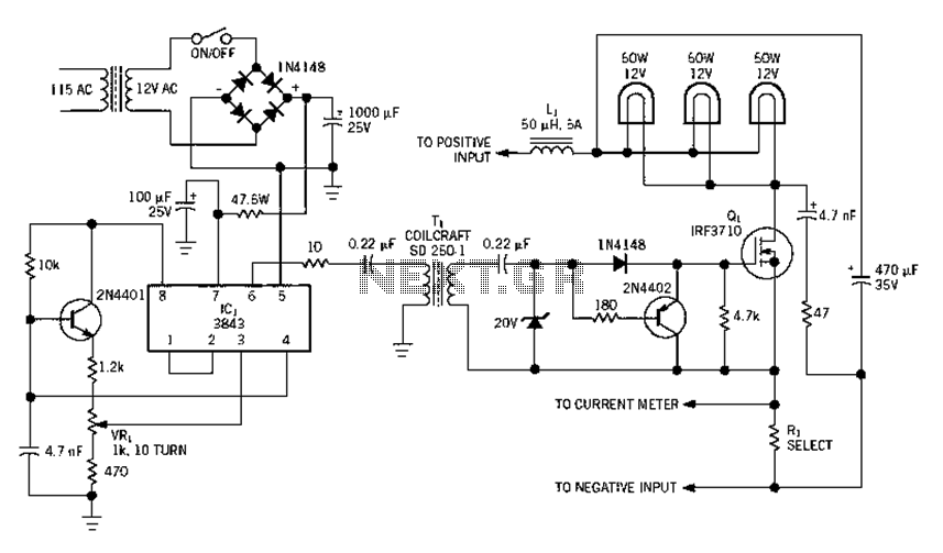
The difference between the amplified signals is utilized to establish the bias for Q1 and Q2 current channels. Q1 regulates the gate-source voltage (VGS) to the necessary level corresponding to the circuit's input and potential output. A 2000 pF...
Warning: include(partials/cookie-banner.php): Failed to open stream: Permission denied in /var/www/html/nextgr/view-circuit.php on line 713
Warning: include(): Failed opening 'partials/cookie-banner.php' for inclusion (include_path='.:/usr/share/php') in /var/www/html/nextgr/view-circuit.php on line 713