
Speakers

The described audio amplifier project utilizes a repurposed DVD player chassis, enhancing its utility by housing an audio amplifier system. The mechanical design includes custom sheet metal braces that provide robust support for heavy components such as the toroidal transformer and filter capacitors. The installation of a 25A rectifier bridge on a heatsink ensures efficient heat dissipation, which is crucial for maintaining performance during operation.
The power supply design is particularly noteworthy, as it incorporates both high and low voltage transformers to cater to different circuit requirements. The inclusion of a 24VCT transformer allows for the safe operation of low-voltage components while ensuring that the high-voltage sections are adequately powered. The adjustment capability in the delay circuit, facilitated by a potentiometer, enhances the versatility of the amplifier, allowing users to customize the delay according to their needs. The LM311 comparator plays a vital role in ensuring reliable logic level transitions, critical for the stability of digital control signals.
Furthermore, careful attention to decoupling and grounding practices is evident, with local capacitance being emphasized to maintain voltage integrity. The strategic grounding method minimizes potential noise issues by preventing ground loops, which is essential for high-fidelity audio applications. The finalization of the amplifier schematic and the forthcoming PCB design signify the project's progression towards completion, promising a well-engineered audio amplifier ready for practical implementation.An old nonfunctional DVD player donated by the Engineering Department was gutted to provide an appropriate enclosure for the audio amplifier. To mount the nearly 16 lb toroidal transformer and 2in diameter filter capacitors, various sheet metal braces were machined in the shop.
The 25A rectifier bridge was bolted to a heatsink attached to the bott om of the enclosure, and a temporary brace was attached to hold the mains power switch and fuse holder. The current state of the amplifier construction process is shown in Figure 1. Because the +12V, -12V, and +5V regulators can only take a maximum of 30V at the input, a smaller 24VCT 700mA frame-type transformer was also mounted to power the lower voltage circuitry (preamplifiers, delay circuitry, output relay controllers).
The delay circuit originally presented was modified to allow for an adjustable delay setting via a potentiometer, and a LM311 comparator was included to make a definite logic level transition. The modified power supply circuit is shown below in Figure 2, and the assembled delay/voltage regulation circuit is shown in Figure 3.
Upon turn on, the delay circuit and main high current power supply worked correctly. Mains unloaded voltage was measured at +/-34VDC, and the smaller power supply produced as expected +12V, -12V, and +5V, as well as the 0-5V logic level delay signal. Since the reservoir capacitance of the small power supply is only 1000uF per rail, local capacitative decoupling will be important for clean voltage levels in the preamplifier circuitry.
To prevent ground loops, the center taps from the transformers are not connected directly to the chassis, but will be linked to the chassis through the circuitry at the point where the audio input connector grounds are attached to the case. This provides most immunity to external interference while preventing a loop antenna from forming that would dramatically degrade noise performance.
Now that the amplifier schematic is more or less finalized and the power supply is built and tested, the amplifier PCB will be designed and sent out for manufacture in the next week. 🔗 External reference
Related Circuits
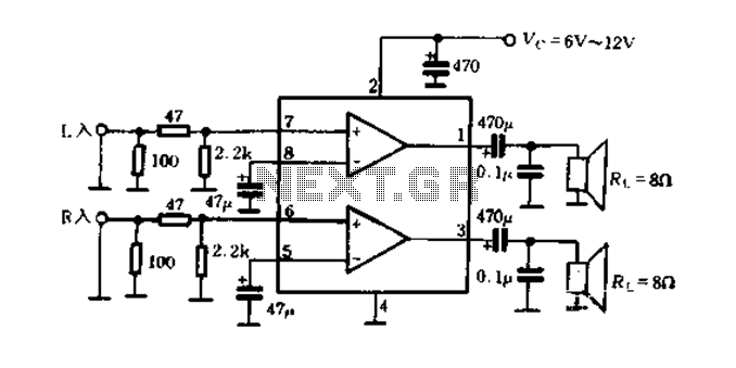
The elements and internal function diagram are depicted in Figure 9-50. Capacitors C1, C2, and C3 represent feedback capacitance, which changes with low-frequency variations within a specific cutoff frequency range. Capacitor C5 serves as the output coupling capacitor, typically...
The short circuit-proof outputs of amplifiers and speakers present intriguing features, including the isolation of the speakers from the amplifier output. The design of short circuit-proof outputs in amplifiers and speakers is crucial for ensuring system reliability and longevity. Such...
Building ESLs involves the use of tools and materials that if handled improperly can be hazardous. Please make sure you know how to use these things before you begin. By all means, use safety glasses at all times. If...
Occasionally, the output volume of an amplifier can be excessively high, leading to discomfort and potential damage to both the listener's ears and the loudspeaker. The circuit... Amplifiers are crucial components in audio systems, responsible for boosting audio signals to...

Attribution is required to give credit to the author or licensor of the work, as specified, without implying endorsement of the user or their use of the work. This file includes additional information, such as EXIF metadata, which is...
The circuit-delay relay for speakers serves as a delay mechanism that prevents the immediate activation of speakers when the amplifier is powered on. This feature is designed to protect the speakers from potential damage caused by sudden power surges....