
Speed control for PCB drill

This circuit employs the ICLM3578 as a key component, which is a versatile and efficient switching regulator. The device's ability to handle separate feedback inputs allows for precise control over the output voltage and current, making it ideal for applications requiring variable speed control, such as in PCB drills. The internal oscillator generates a PWM signal, which is modulated by the timing capacitor C2. The frequency of this PWM signal is critical, as it directly influences the responsiveness and smoothness of the motor speed control.
The resistors R1 and R2 play a vital role in defining the duty cycle of the PWM signal. By adjusting the potentiometer R2, the user can fine-tune the resistance, thereby altering the duty cycle and, consequently, the average voltage supplied to the motor. This feature allows for a wide range of speed control, accommodating different operational requirements of the PCB drill.
Transistor Q1 acts as a switch that responds to the PWM signal, effectively controlling the power delivered to the motor M. The use of a MOSFET for this application is advantageous due to its high efficiency and fast switching capabilities, which are essential for maintaining performance during variable speed operations.
The inclusion of diode D1 as a freewheeling diode is crucial for protecting the circuit from voltage spikes that can occur when the motor is turned off. These transients can potentially damage the switching components, so the diode provides a safe path for the current to dissipate.
Finally, capacitor C3 serves as a filter capacitor to smooth out any voltage fluctuations, ensuring stable operation of the circuit. This combination of components results in a robust and efficient design for controlling the speed of DC motors in PCB drilling applications.Here is a simple circuit for controlling the speed of DC operated PCB drills. The heart of this circuit is the ICLM3578 which is a very efficient integrated switching regulator that can be used for applications like this. The LM3578 has separate inverting and non inverting feedback inputs (pin1 and pin2), 1V internal reference voltage source and a
built in oscillator circuit. The IC can be configured to obtain up to 90% duty cycle. In the circuit, capacitor C2 is the timing capacitor which determines the frequency of the internal oscillator. The duty cycle depends on the sum of resistors R1 and R2 and it can be varied by adjusting the POT R2.
The output PWM signal will be available at pin 5 of the IC. The Q1 drives the motor M according to the PWM signal available at pin5 and thus by varying the duty cycle of the PWM wave by varying POT R2, the speed of the motor can be adjusted. The diode D1 is a freewheeling diode which protects the MOSFET Q1 from transients produced by the motor.
Capacitor C3 is just a filter capacitor. 🔗 External reference
Related Circuits
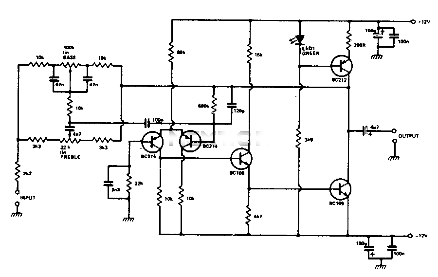
The circuit utilizes an inverting operational amplifier configuration with discrete transistors to address issues such as inadequate slew rate, significant distortion, and elevated noise levels. The output stage is powered by a constant current source, which is biased using...
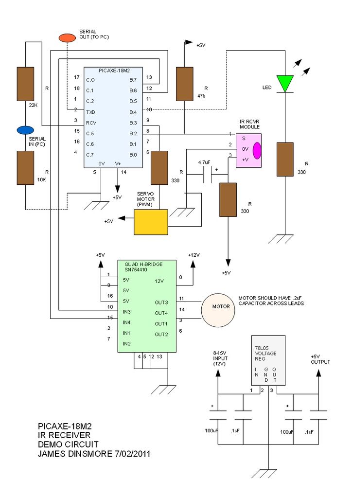
The PICAXE basic code is straightforward: the main loop continuously checks for a signal from the IR receiver using the irin command. When a code is received, it is stored in... The PICAXE microcontroller is designed for simplicity and ease...
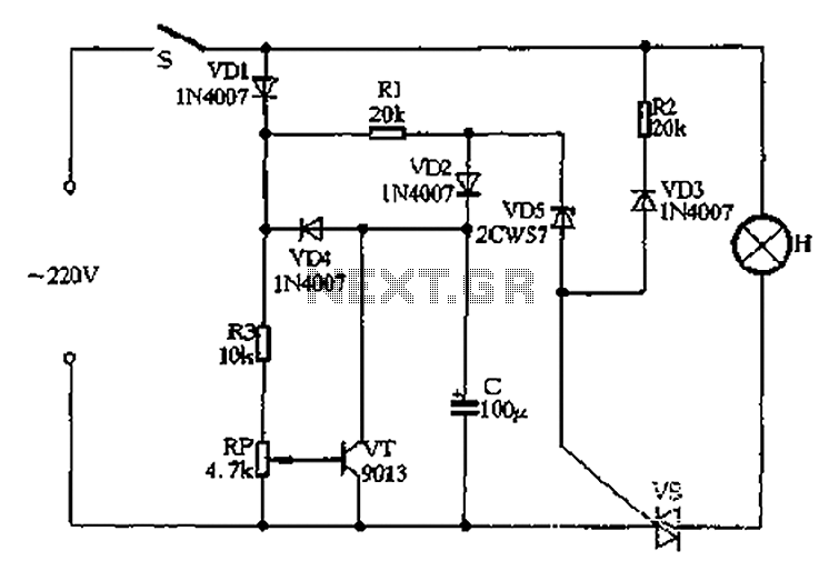
Closing switch S allows the power supply's positive half cycle to flow through VD1, R1, and VD2 to charge capacitor C. The voltage across capacitor C gradually increases but remains significantly lower than the threshold voltage of the zener...
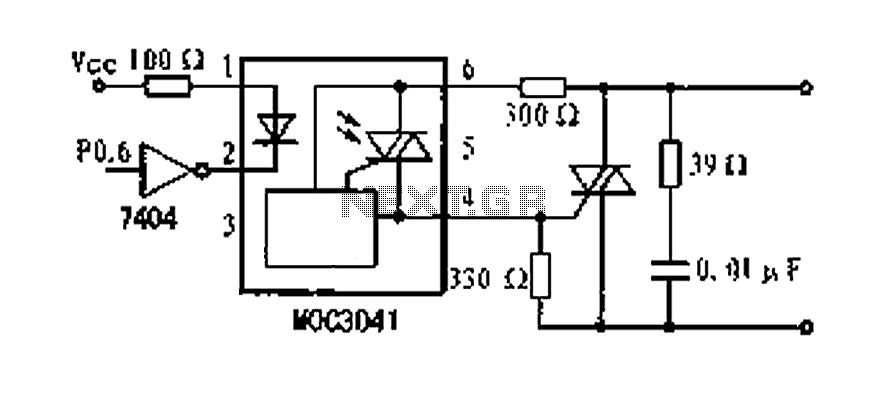
A dimming control circuit is implemented using a single-chip I/O port sinking method to control a thyristor switch for dimming functionality. The MOC3041 optocoupler features an internal zero-crossing detection circuit, allowing for effective control of the thyristor. This design...
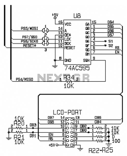
This circuit is designed for interfacing an I/O keypad and an LCD, allowing students to gain hands-on experience with basic I/O device interfacing using the HCS12 microcontroller mounted on the CML12S-DP256 development board. The keypad utilized in this circuit...
The following circuit illustrates a Radio Remote Control Circuit Diagram. This circuit is based on the UM91214B IC. Features include the use of DTMF (dual-tone multi-frequency) technology. The Radio Remote Control Circuit utilizes the UM91214B integrated circuit, which is specifically...