
UM91214B IC For Radio Remote Control
The Radio Remote Control Circuit utilizes the UM91214B integrated circuit, which is specifically designed for DTMF applications. In this configuration, the circuit is capable of receiving DTMF signals transmitted from a remote control unit, allowing for the control of various devices wirelessly.
The circuit typically consists of a transmitter and a receiver. The transmitter includes a keypad that generates DTMF tones when buttons are pressed. These tones are then modulated onto a radio frequency (RF) carrier signal, which is transmitted over the air. The receiver, which incorporates the UM91214B IC, demodulates the incoming RF signal and decodes the DTMF tones back into their original binary format.
Key components of the circuit include an RF transmitter module, an RF receiver module, the UM91214B IC, a microcontroller for processing the decoded signals, and output drivers that control the devices being operated. Power supply considerations are also essential; typical configurations utilize a regulated power source to ensure stable operation of the circuit.
The design allows for multiple control commands to be sent simultaneously, making it suitable for applications such as remote lighting control, garage door openers, and other home automation tasks. The circuit’s range, reliability, and ease of use make it an effective solution for wireless control applications.The following circuit shows a Radio Remote Control Circuit Diagram. This circuit based on the UM91214B IC. Features: use of DTMF (dual-tone .. 🔗 External reference
Related Circuits
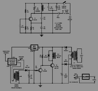
This circuit of an FM radio-controlled anti-theft alarm can be utilized with any vehicle that has a 6 to 12-volt DC supply system. The mini VHF FM transmitter is installed in the vehicle during the night when it is...
The L29 Stepper Motor Controller IC facilitates the control of four drive signals for two bipolar and four unipolar footfall motors in a microcomputer-controlled appliance. It allows for motor operation in half-step, full-step, and wave drive modes, utilizing switch-mode...

This area is primarily characterized by commercial information resellers. A notable exception is Nostalgia Air, which maintains an expanding database of radio schematics. Some links provided here direct to Nostalgia Air's database; however, if the desired information is not...
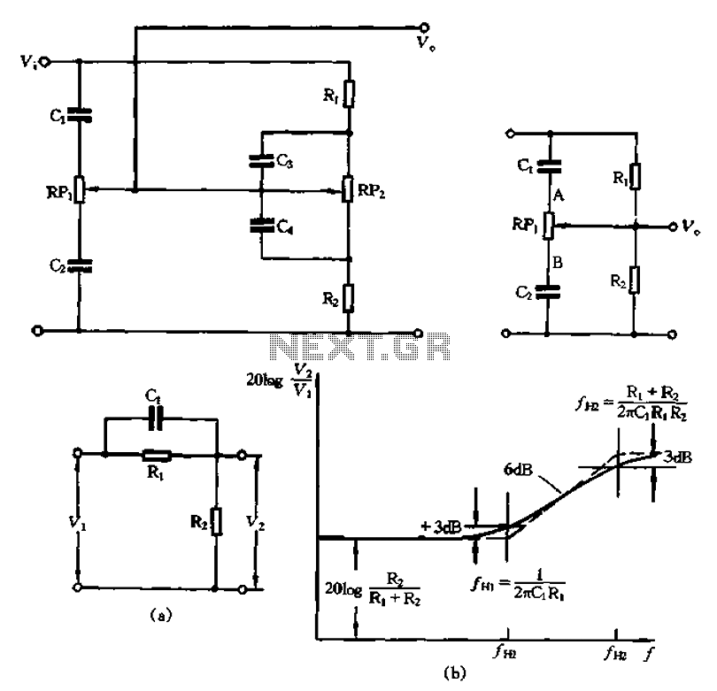
The circuit illustrated in Figure 1-560 represents a treble control potentiometer. Due to the larger capacitance values of C3 and C4 compared to C1 and C2, high-frequency signals can treat C4 as a short circuit. Consequently, the treble adjustment...
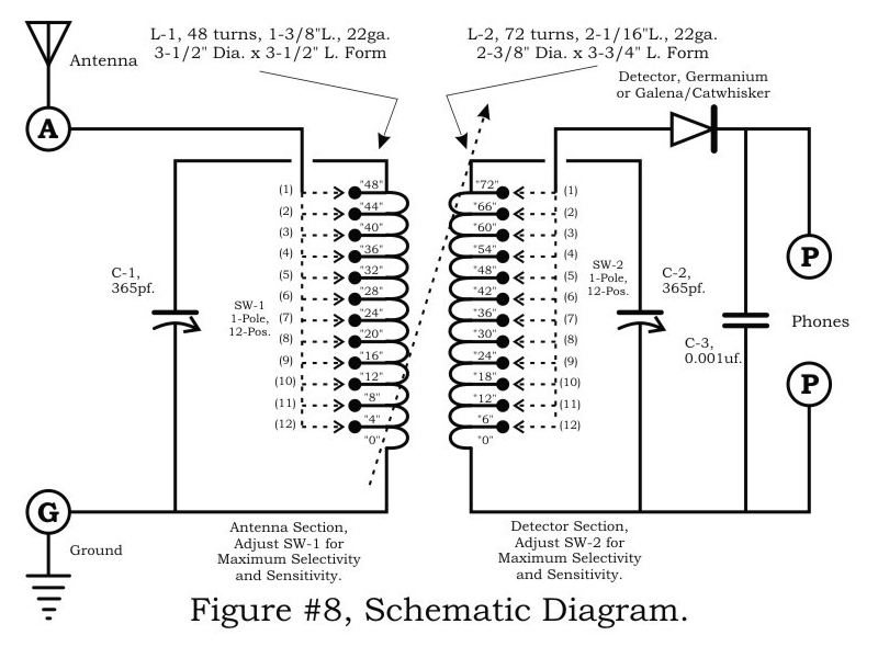
A two-circuit tuner, similar to a loose coupler, is an effective method for achieving selectivity without compromising sensitivity. The circuit introduces the signal to the primary antenna section via the SW-1 arrangement, allowing the antenna to be matched to...
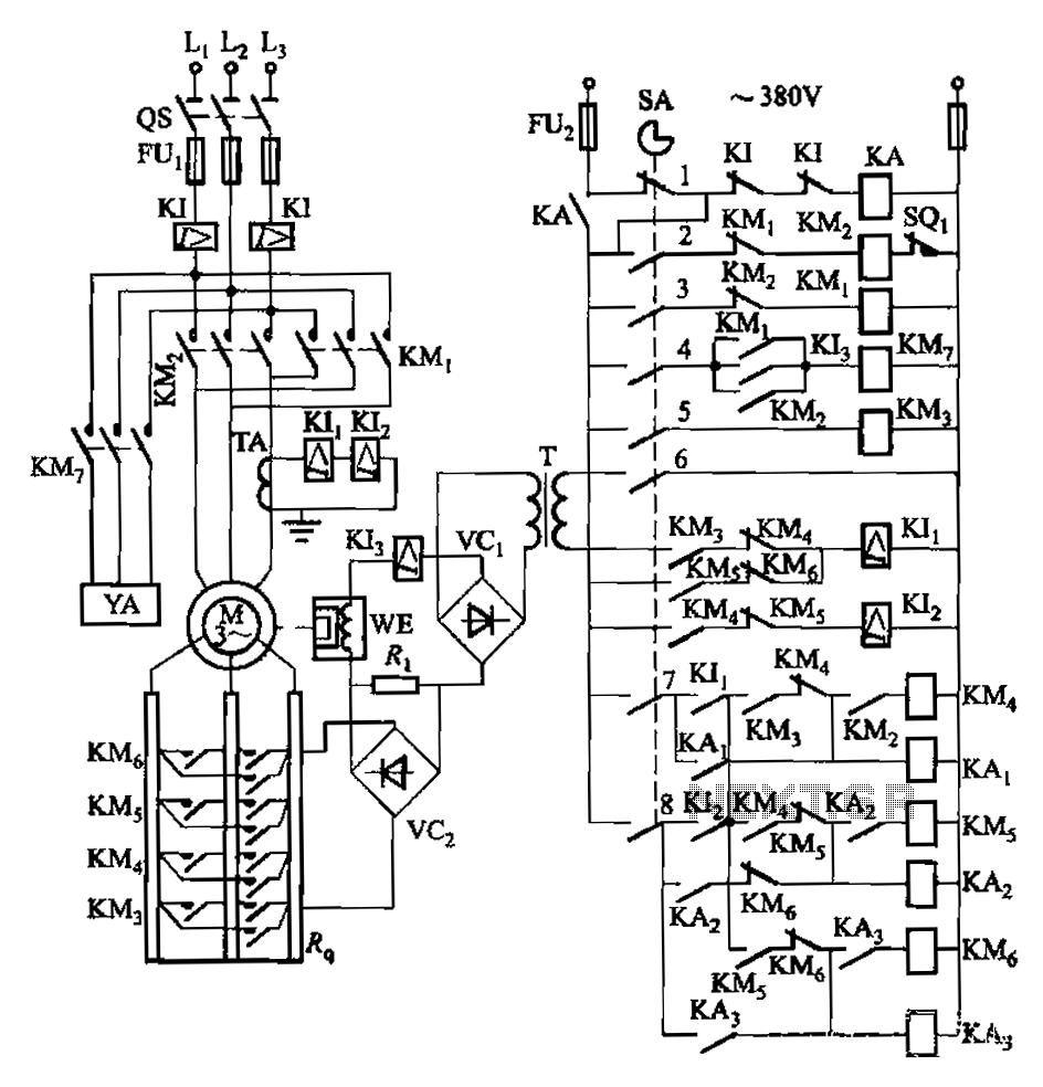
Attached to the wall is a high-rise building construction elevator, an essential piece of vertical transportation machinery. Its drive motor is typically a wound wire induction motor. The main switch and eddy current brake controls are also mounted on...