
Speed Control of DC Motor using Microcontroller 8051 withCircuit
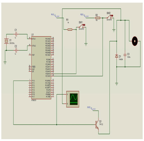
The circuit for this DC motor speed control project consists of several key components: a DC motor, a microcontroller (AT89C51), a power supply, a transistor (typically an NPN type), and a PWM driver circuit. The microcontroller is programmed to output a PWM signal that controls the base of the transistor, which acts as a switch to modulate the power supplied to the motor.
In operation, the microcontroller generates a PWM signal with a specific duty cycle. The duty cycle determines the proportion of time the signal is High versus Low, effectively controlling the average voltage and current supplied to the motor. A higher duty cycle results in increased average voltage, thereby increasing the motor speed, while a lower duty cycle decreases the average voltage and slows the motor down.
The transistor is connected in such a way that it can handle the current required by the motor. When the PWM signal from the microcontroller is High, the transistor turns on, allowing current to flow through the motor. When the PWM signal is Low, the transistor turns off, stopping the current flow. This rapid switching creates the effect of varying the motor speed without the need for complex mechanical systems.
Additional components may include diodes for flyback protection, which prevent back EMF generated by the motor from damaging the transistor and microcontroller. A capacitor may also be included to filter the PWM signal, ensuring smoother operation of the motor.
Overall, this circuit design provides a robust solution for controlling the speed of a DC motor using modern electronic components, allowing for efficient and precise adjustments based on user-defined parameters. The integration of a microcontroller enhances flexibility and programmability, making it suitable for a variety of applications in automation and robotics.The aim of developing this project is to control the speed of DC motor. The main advantage in using a DC motor is that the Speed-Torque relationship can be varied to almost any useful form. To achieve the speed control an electronic technique called Pulse Width Modulation is used which generates High and Low pulses.
These pulses vary the speed in the motor. For the generation of these pulses a microcontroller (AT89c51) is used. As a microcontroller is used setting the speed ranges as per the requirement is easy which is done by changing the duty cycles time period in the program. This project is practical and highly feasible in economic point of view, and has an advantage of running motors of higher ratings.
This project gives a reliable, durable, accurate and efficient way of speed control of a DC motor. 🔗 External reference
Related Circuits
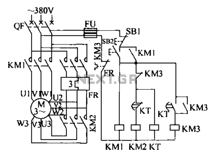
The extended delta decompression starter is designed to manage the operation of a three-phase motor during startup. It involves the initial connection of the motor's three-phase winding set to facilitate a reduced voltage startup, which is achieved through a...
The schematic depicts standard light bulbs, indicating the possibility that some bulbs may be burned out. It is currently unclear whether the bulbs can be easily replaced. Further inspection reveals that the bulbs in the HVAC control can indeed...
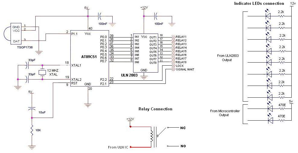
To control multiple switches, it is necessary to transmit several bits via infrared (IR) transmission to indicate which key is pressed on the remote control and, consequently, which switch on the switchboard to operate. This project utilizes a commercially...
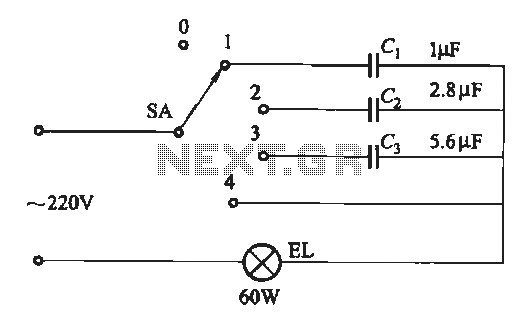
A dimming circuit capacitor circuit is illustrated in Figure 2-63. When the switch SA is moved from position "1" to "3," the capacitance increases in ascending order, resulting in the light bulb brightness also increasing correspondingly. When SA is...
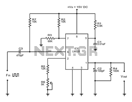
The LM331 is a precision voltage-to-frequency converter developed by National Semiconductors. This integrated circuit (IC) has various applications, including analog-to-digital conversion, long-term integration, voltage-to-frequency conversion, and frequency-to-voltage conversion. Its wide dynamic range and excellent linearity make it suitable for...
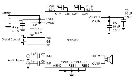
The NCP2830 audio power amplifier features high-quality audio performance with a total harmonic distortion plus noise (THD+N) of 0.04%. It offers low noise with a signal-to-noise ratio (SNR) of up to 100 dB and optimizes overall system efficiency, achieving...