
Frequency to voltage converter using LM331
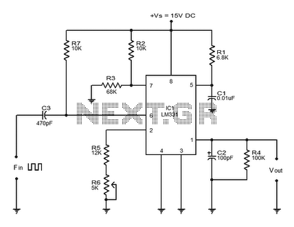
The LM331 integrated circuit operates based on the principle of converting frequency signals into corresponding voltage levels, making it a versatile component in various electronic systems. The architecture of the circuit typically includes several key components: a capacitor (C3) that differentiates the input frequency signal, a resistor (R7) that helps shape the pulse train, and the timing components (R1 and C1) that define the response characteristics of the circuit.
When the input frequency signal is applied, the capacitor (C3) serves to differentiate the signal, producing a pulse train that represents the changes in the frequency over time. This pulse train is then directed to pin 6 of the LM331, where the threshold comparator monitors the signal. The negative edges of the pulse train trigger the internal comparator, which activates the timer circuit within the IC.
The output current from pin 6 of the LM331 is directly influenced by the input frequency and the timing components. As the input frequency increases, the current output also increases proportionally, thereby generating a corresponding output voltage (Vout) across the load resistor (R4). This output voltage can be utilized in various applications, such as analog-to-digital conversion systems, where it can be further processed or displayed.
In summary, the LM331 serves as a precise and efficient means of converting frequency signals into linear voltage outputs, making it an essential component in modern electronic design and applications. Its ability to maintain excellent linearity and wide dynamic range enhances its usability in various measurement and control systems.LM331 is basically a precision voltage to frequency converter from National Semiconductors. The IC has a hand full of applications like analog to digital conversion, long term integration, voltage to frequency conversion, frequency to voltage conversion. Wide dynamic range and excellent linearity makes the IC well suitable for the applications men tioned above. Here the LM331 is wired as a frequency to voltage converter which converts the input frequency into a proportional voltage which is extremely linear to the input frequency. The frequency to voltage conversion is attained by differentiating the input frequency using capacitor C3 and resistor R7 and feeding the resultant pulse train to the pin6 (threshold) of the IC.
The negative going edge of the resultant pulse train at pin6 makes the built-in comparator circuit to trigger the timer circuit. At any instant, the current flowing out of the current output pin (pin 6) will be proportional to the input frequency and value of the timing components (R1 and C1).
As a result a voltage (Vout) proportional to the input frequency (Fin) will be available across the load resistor R4. 🔗 External reference
Related Circuits
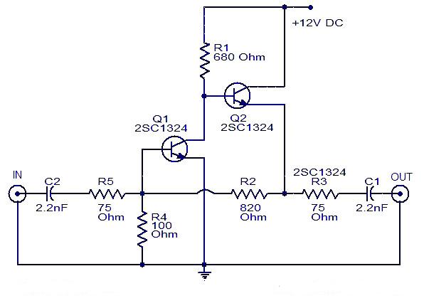
This is a cable TV amplifier utilizing two transistors. The amplifier circuit is designed for cable TV systems using 75 Ohm coaxial cables and operates effectively up to 150 MHz. Transistor T1 is responsible for amplification, providing an expected...
The circuit presented utilizes modulated rectangular waves of varying time periods to generate ringing tones akin to those produced by a telephone. It requires four astable multivibrators for operation, implemented using two 556 integrated circuits (ICs). The 556 IC...
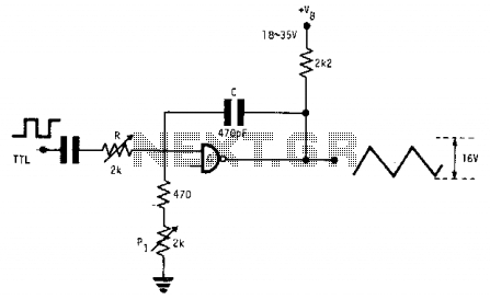
This fixed-frequency triangular waveform generator, driven by a TTL square wave, produces triangular waveforms with a peak-to-peak voltage of typically 16 V at frequencies reaching several MHz. The design utilizes a single AND open collector gate or an open...
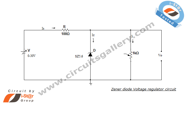
A Zener diode regulator is a fundamental electronic circuit valuable for hobbyists. This circuit provides a regulated output voltage, suitable for biasing other circuit components. The Zener diode operates in the reverse breakdown region, maintaining a nearly constant voltage...
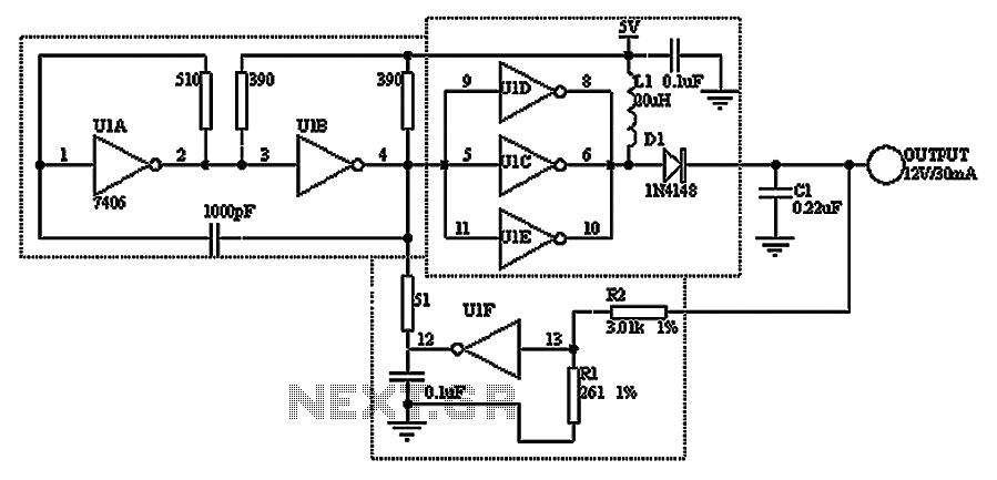
A TTL hex inverter circuit can function as a DC/DC converter, converting 5V to 12V. This circuit encompasses all necessary functionalities for DC/DC conversion. It relies on a TTL switching threshold voltage regulator. The components U1A and U1B form...
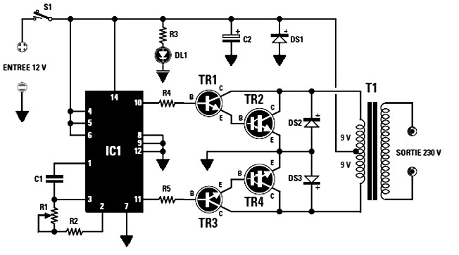
The final power transistors TR2 and TR4 must be mounted on appropriately sized heatsinks to prevent overheating. Suitable options include MJ4033, MJ3007, or other NPN transistors. The maximum power output is dependent on the transformer T1's core size. For...