
ir remote controlled switchboard rc5
To implement this circuit effectively, the following components and connections are essential:
1. **IR Remote Control**: The remote control must be compatible with the RC5 protocol, ensuring that it can send the necessary 14-bit data when a button is pressed.
2. **TSOP1738 IR Receiver**: This component receives the modulated IR signal from the remote control. It is critical for converting the IR light signal into an electrical signal that can be processed by the microcontroller. The TSOP1738 is designed to demodulate signals at the specified carrier frequency of 36-38 kHz.
3. **AT89C51 Microcontroller**: This microcontroller is responsible for decoding the received serial data. The microcontroller should be programmed to interpret the 14-bit data format, extracting the address and data bits to determine which switch to activate.
4. **ULN2803 Driver IC**: This is a high-voltage, high-current Darlington transistor array used to drive the relays. It allows the microcontroller to control multiple relays without exceeding its output current limitations.
5. **Relays**: The relays serve as the switching elements that control the actual load or switchboard. Each relay corresponds to a particular switch, and the microcontroller activates the appropriate relay based on the decoded data.
6. **Power Supply**: Ensure that all components are powered adequately. The microcontroller and receiver typically operate at 5V, while the relays may require a higher voltage depending on their specifications.
7. **Circuit Connections**:
- Connect the output of the TSOP1738 to one of the input pins of the AT89C51.
- Program the microcontroller to read the incoming data and determine which relay to activate.
- Connect the outputs of the AT89C51 to the input pins of the ULN2803.
- Connect the outputs of the ULN2803 to the relays, ensuring that the relays are connected to the appropriate load or switchboard.
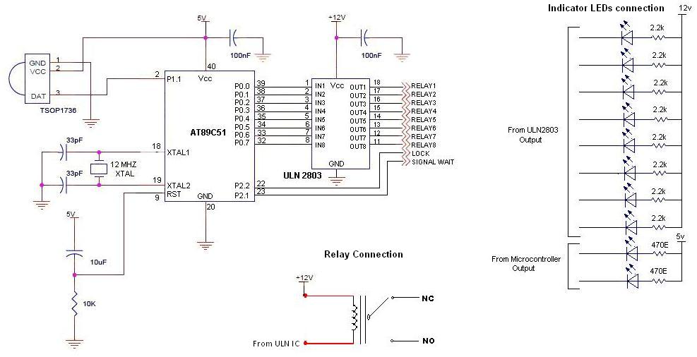
This schematic design allows for effective control of multiple switches using a simple IR remote control, leveraging the well-established RC5 protocol for reliable communication.As more than one switches are to be controlled, we have to transmit a number of bits through IR transmission to indicate which is key is pressed on the remote and accordingly which switch of the switch-board to control. In this project, this is done by using a ready-made IR remote control which works on RC5 protocol. RC5 protocol was developed by Phillips for controlling consumer electronics such as TV, VCD-DVD Player, etc. through IR Remote Controller. This type remote controller can be found in Phillips` 90 channel TVs. This is a very popular IR protocol and very easy to understand. Basically, in a RC5 protocol, when a key on the remote controller is pressed, a total of 14 bits are serially transmitted. This includes 2 Start bits, 1 Toggle bit, 5 Address bit and 6 Data bit. These 14 bits are transmitted on a carrier of 38/36 khz carrier by using Manchester Coding. High and Low time are 889 us. For more on Manchester Coding and RC5 protocol, read this. At the receiver, TSOP1738 receiver is used. It removes the carrier and provides serial data. This serial data is applied to AT89C51 microcontroller for decoding serially transmitted data and control the output accordingly.
Relays are used for switching action and they are controlled by the microcontroller through the ULN2803 IC. Circuit diagram is shown below : 🔗 External reference
Related Circuits
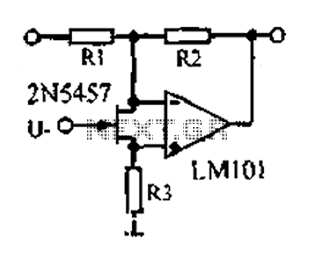
A 1.53 voltage-controlled gain amplifier (VGA) utilizes a FET connected between the two inputs of the operational amplifier (op-amp) as a voltage-controlled resistance. The resistance changes linearly with voltage and varies from several dozen square ohms, exhibiting excellent control...
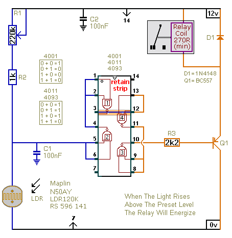
The first circuit energizes the relay when the light rises above the preset level. The second circuit energizes the relay when the light falls below the preset level. The two circuits are practically identical. The only difference between them...
The circuit of an FM Tracking Transmitter Circuit or Remote Control Transmitter Circuit is explained using a 555 IC and 2N4392 transistors. The FM Tracking Transmitter Circuit utilizes a 555 timer integrated circuit (IC) configured in astable mode to generate...
Each unit features four channels, enabling the programming and operation of up to four separate devices with a single remote, provided these devices operate on the same frequency. The unit can automatically learn from existing garage door remotes or...
The integrated circuit input side contains an oscillating circuit, where the oscillation frequency is determined by the external components L1, C1, and the sensor's equivalent capacitance. The equivalent capacitance increases as the sensor is immersed in liquid. The oscillating...
Early transmitters using LC oscillators experience significant frequency drift. The introduction of Surface Acoustic Wave (SAW) devices addresses this issue, providing substantial frequency stability comparable to crystals. These devices can achieve fundamental frequencies in the hundreds of megahertz or...
Warning: include(partials/cookie-banner.php): Failed to open stream: Permission denied in /var/www/html/nextgr/view-circuit.php on line 713
Warning: include(): Failed opening 'partials/cookie-banner.php' for inclusion (include_path='.:/usr/share/php') in /var/www/html/nextgr/view-circuit.php on line 713