
Spider robot with PIC16F84
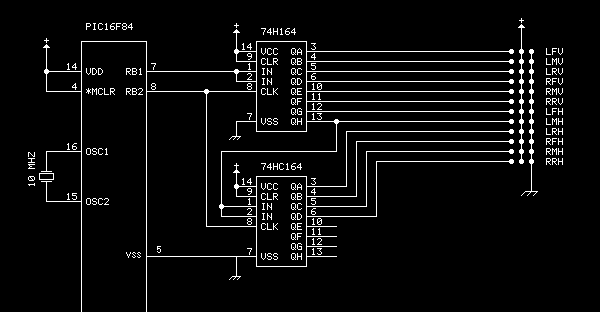
The circuit design utilizes a PIC microcontroller interfaced with two 74HC164 shift registers to control a total of twelve servos. The 74HC164 is a serial-in, parallel-out shift register that allows for efficient data management. The PIC microcontroller sends data and shift signals to the first shift register, which receives a single bit of data representing the desired position of each servo. The shift register then propagates this data to the second shift register in a cascading manner, enabling the control of multiple servos with minimal pin usage on the PIC.
The servos operate with a 5V power supply, which is provided by a battery pack composed of four AA nickel-metal hydride (NiMH) batteries. This configuration allows the servos to achieve their required torque while drawing minimal current when stationary, approximately 10 mA. The design of the HEXBOT incorporates a dual-axis movement system for each leg, with one servo controlling lateral movement and another controlling vertical movement. This dual configuration is crucial for achieving complex locomotion, including walking and turning maneuvers.
The mechanical design of the HEXBOT has been optimized to minimize power consumption. The use of aluminum angle stock for the legs provides a lightweight yet sturdy framework, reducing the load on the servos compared to earlier designs that utilized heavier materials. The joints are assembled using #6 screws and plastic-insert nuts, allowing for a balance between rigidity and flexibility, which is essential for the dynamic movement of the robot.
Overall, this schematic design showcases an efficient method of servo control using a microcontroller and shift registers, combined with a thoughtfully engineered mechanical structure that promotes optimal performance and energy efficiency in robotic movement.To get enough outputs from the PIC chip, a pair of 74HC164 shift registers was used. These need only two lines from the PIC (data & shift) to produce the twelve signal pulses for the servos. A single bit is shifted into the first shift register, then, after a specific delay, it is shifted to the next servo.
The second shift register cascades off the first. This system can be extended for any number of servos. The idea of this design is that no power is needed when the legs are in the full down position. They also create a lot of extra leverage at the bottom of travel. This helps overcome friction as the leg is moving horizontally inward at this time. When the leg is raised, the velocity increases with height making it easy to raise the leg over an inch. The platform on top holds the downloader board when trying out new code. The full schematic is available for download as is the source listing. As of this point, I have worked out walking forward and backward, and turning left and right. The rest, as they say, is left as an exercise for the student. The HEXBOT is constructed from 12 (cheap) model airplane servos. Each leg moves laterally on one servo and vertically on the other. Conveniently, this type of servo runs on 5 volts. These servos need only a specific width pulse to position it. Once it arrives at its target location, it draws very little power (about 10 ma). Power is provided by a set of four AA metal hydride batteries mounted underneath. Neither the servos or the PIC requires highly regulated power. An earlier version of the hexbot had legs made out of 1/4 inch aluminum square stock with a 90 degree bend. This caused the vertical servos to draw a lot of power just standing still. It could barely walk. The new leg design uses a piece of 1/2 inch aluminum angle stock (see the close-up), and two peices of the 1/4 inch square stock.
The parts are joined with #6 screws and those plastic-insert 'aircraft' nuts. The nuts are tightened just enough to take up the slop but still allow movement. 🔗 External reference
Related Circuits
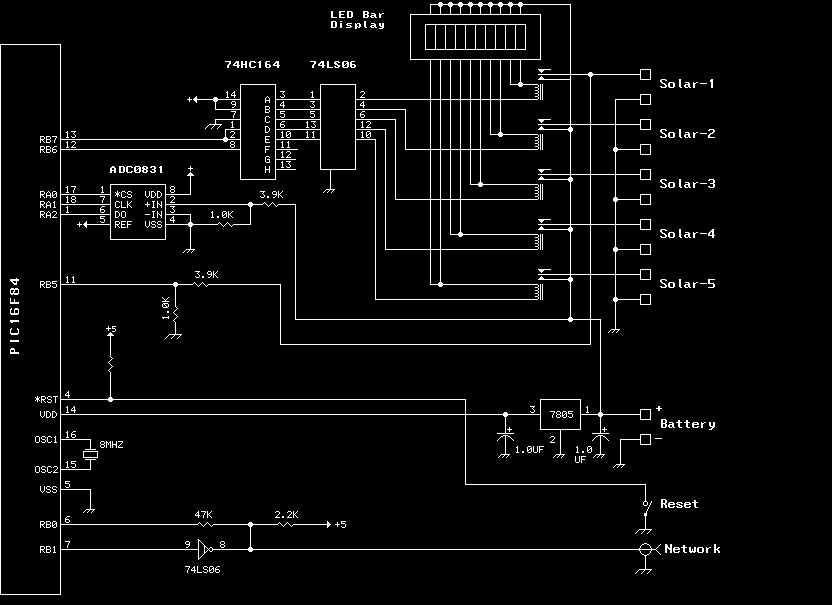
The previous version of this device used pulse width modulation (PWM) to control the power from the five solar panels to charge the battery bank. Under full sun conditions, the MOSFETs got a bit warm and the whole unit...
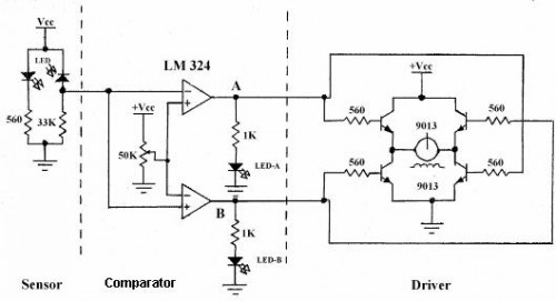
Line follower robots are commonly designed to follow a specific path on a track. Typically, these robots are controlled by microcontrollers; however, this article discusses a line follower robot designed without using a microcontroller. The assembly consists of three...
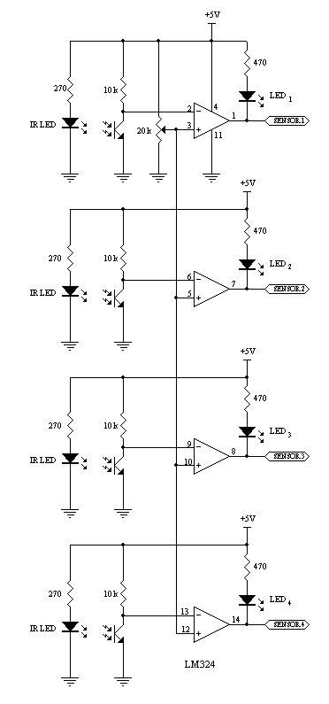
This robot utilizes two motors to control the rear wheels, while the single front wheel is free to move. It is equipped with four infrared sensors located on the underside to detect black tracking tape. When the sensors identify...
The objective of this project is to consolidate various robot designs and transform them into a new device featuring updated hardware and standardized software, specifically utilizing Arduino for ease of use. These robots share three key components: a mechanical...
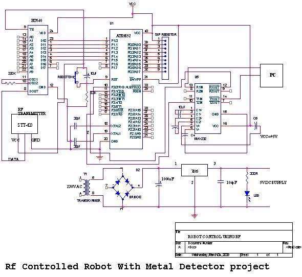
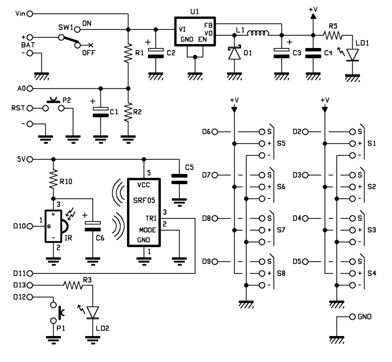
An embedded C-based RF-controlled robot equipped with a metal detector, along with wireless image and voice transmission capabilities. This project report is intended for electronics and communication engineering students. The project involves the design and implementation of an RF-controlled robot...
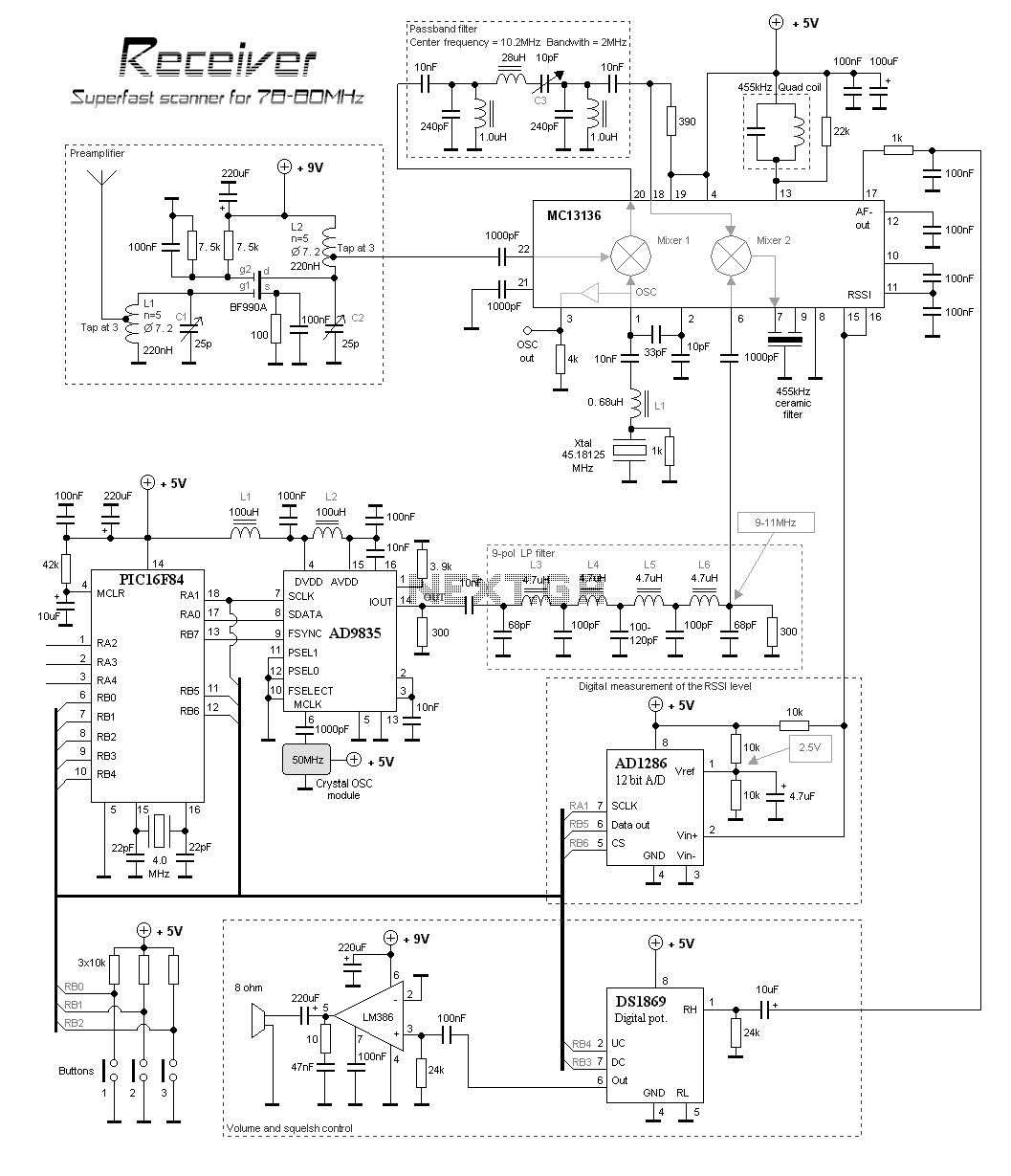
This scanner uses a DDS circuit to scan through the frequency band. Since a DDS is used to set the desired frequency, this receiver can jump from one frequency to another within microseconds, making it very fast. The receiver...