
Robot shield for Arduino

Arduino can be powered through the plug with a voltage between 6 to 12 volts, his voltage regulator provides the 5 V stabilized, necessary for the operation of our shield. We could power our robot with rechargeable batteries. A standard servo requires a supply voltage of 4. 8 to 6 volts, easily obtainable with four batteries in series, at full charge, provide 1. 5 x 4 = 6 volts but towards the complete discharge provide just 1. 0 x 4 = 4 volts. We are not in optimal conditions for the servos. Throughout this reasons we decided to create a special shield, already prepared for all these functions, it is easy to install and use.
We can assume to power our robot with a single battery pack with a voltage between 6 and 12 volts, so for example two cells or 6-8 LiPo NiMh or NiCd cells. The servos works at 5Volt, so we should get this stabilized voltage starting from input voltage of 6-12 volts.
The optimal solution is the use of a switching step-down regulatorwhich ensures efficiency exceeding 80% in every situation. Just the integrated LM2576-5 contains all the elements to build a switching power supply, just add an inductor, a diode and a capacitor.
It can deliver a maximum current of 3A and accepts input voltages between 4 and 40volt. Analysing the wiring diagram you can see the connector BAT which will connect the battery pack to the switch and the voltage regulator LM2576, the resistance R5 and the led LD1 are used only to detect the presence of the voltage. The stabilized voltage output from the LM2576 will be used to power all the servos, while the Arduino is powered directly from the battery pack, taking the tension just after the switch (Vin).
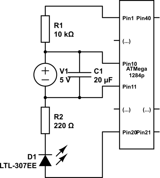
For reading the battery voltage will use an analog input of Arduino (A0). The two resistors R1 and R2 reduce the voltage to a value between 0 and 20 volts to a value of 0-5Volt. We chose these specific values of resistance because, by reading the analog voltage with Arduino, it is sufficient to divide the data acquired by 50 to obtain the value of the voltage in volts.
As obstacle sensor we chose the ultrasonic sensor model SRF05 that, thanks to its shape, recalls two eyes and improves the aesthetic appearance of our robot. To operate, we use a digital line connected to PIN11. As remote control we opt for a economical infrared system; is sufficient to install an IR receiver compatible with the normal commercial remote controls, such as the integrated PNA4602.
It will be sufficient a normal remote control of those used for TVs or VCRs to send commands to our robot in a simple and economic way. The shield provides the Arduino reset button, a button for general use and a LED connected to pin 13 of Arduino.
Filippo is a biped robot whose movements are assigned to only two servos, but with this robot you can experiment with robotics without spending large sums. It is able to walk and turn around, then you can direct it in any direction, enabling those who are beginning to become familiar with the servos and how they can interact with mechanical parts.
Its assembly is facilitated because all the pieces fit over each other and it is sufficient sorder to fix them permanently, as an alternative you can use the epoxy glue. Afte 🔗 External reference
Related Circuits
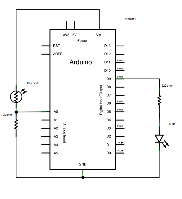
This example demonstrates a technique for calibrating sensor input. The Arduino takes sensor readings for five seconds during startup and tracks the highest and lowest values obtained. These sensor readings during the first five seconds of the sketch execution...
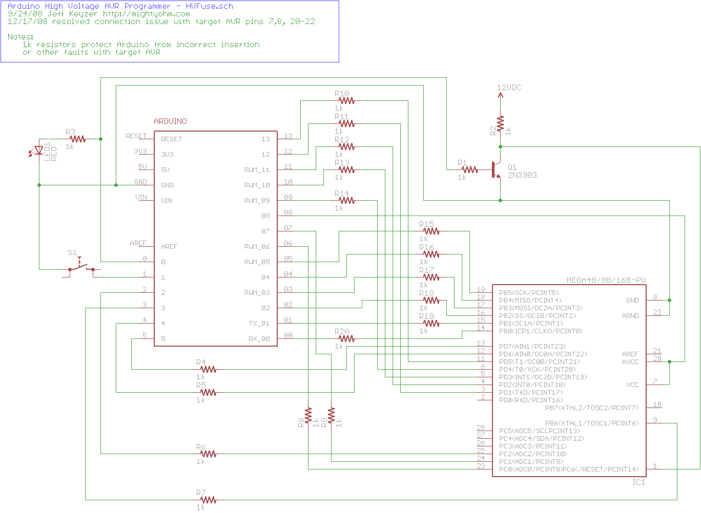
The project explains how to create a simple AVR High Voltage Programmer using Arduino. It can be utilized to fix or recover incorrectly fused AVR chips. The AVR High Voltage Programmer is designed to reprogram AVR microcontrollers that have been...

The USB to RS232 converter is called USB-2-bot and comes from another project. Any other converter would work as well, e.g. this USB-TTL-232-cable from adafruit. It has an ISP connector to program the bootloader and a serial connection used...
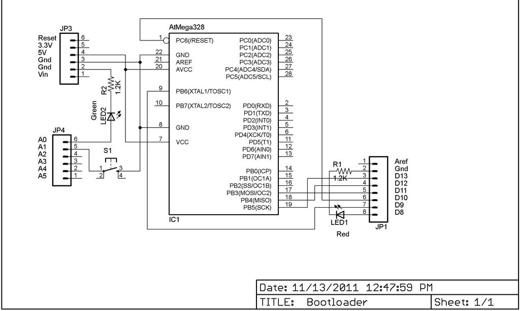
This Lazy Old Geek is also an Arduino enthusiast. One of the common microcontrollers used by Arduinos is the Atmega328 chip. To utilize Arduino software, the Atmega must be equipped with bootloader software. There is a notable difference between...
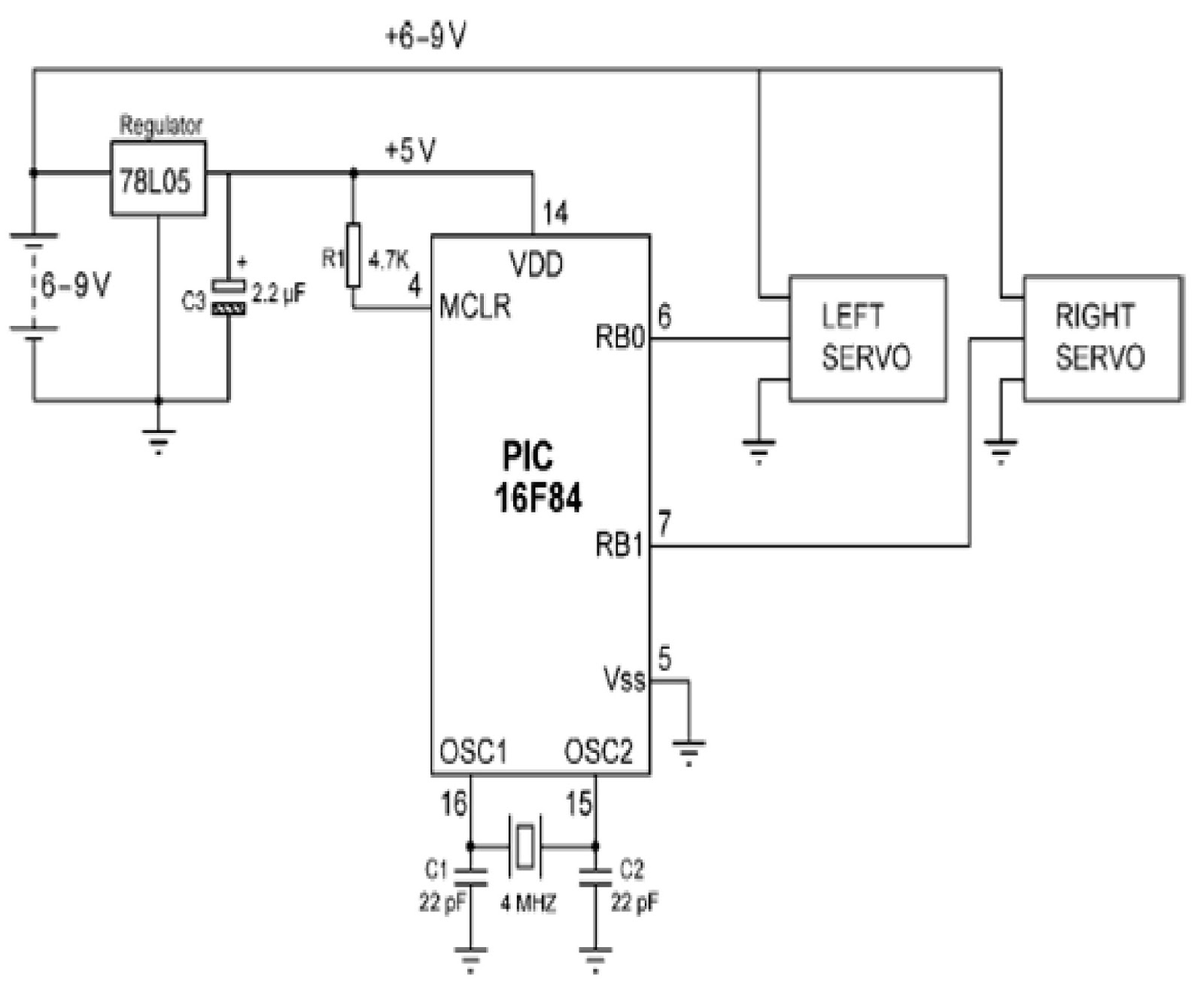
Mobile robots are utilized in various industrial, commercial, research, and hobby applications. This project focuses on controlling a mobile robot using servomotors. The robot is based on a well-known mobile robot called Boe Bot, developed by Parallax. The basic...
Program an ATmega1284P using an AVR Dragon and the Arduino IDE. The mighty1284p library has been installed, and after writing the sketch, it is compiled using the Arduino IDE. The compilation process creates a hex file in a temporary...