
Spike Detector For Oscilloscopes

Dynamic flip-flops are a specific type of sequential logic circuit that utilize dynamic storage techniques to hold state information. Unlike static flip-flops, which maintain their state as long as power is supplied, dynamic flip-flops require periodic refreshing of their stored information. This characteristic allows dynamic flip-flops to achieve higher density and faster operation, making them suitable for applications where space and speed are critical.
However, dynamic flip-flops have limitations, particularly regarding input signal requirements. They are designed to ignore input pulses that fall below a specified duration, typically 40 ns, which helps to filter out noise and ensure that only valid signals are processed. Additionally, the requirement for TTL levels means that the input signals must conform to specific voltage thresholds defined by the Transistor-Transistor Logic (TTL) standard. Signals that do not meet these criteria may lead to unpredictable behavior or erroneous state changes.
When designing circuits that incorporate dynamic flip-flops, it is essential to consider the timing characteristics of the input signals. Proper signal conditioning may be necessary to ensure that input pulses meet the required duration and voltage levels. Furthermore, the choice of dynamic flip-flops should align with the overall circuit design goals, particularly in high-speed applications or where space constraints exist.
In summary, while dynamic flip-flops offer advantages in speed and density, careful attention must be paid to input signal characteristics to ensure reliable operation in electronic circuits.Dynamic flip-flops ignore pulses at their inputs that are shorter than 40 ns or do not have TTL levels. This means that TTL flip-flops are poorly suited to.. 🔗 External reference
Related Circuits
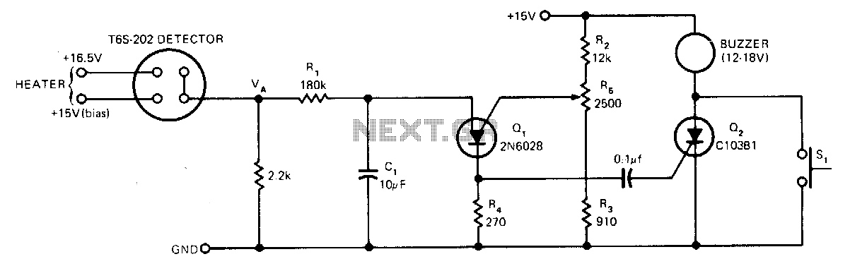
The sensor operates based on the selective absorption of hydrocarbons by an n-type metal-oxide surface. The device features a heater designed to eliminate hydrocarbons once smoke or gas is no longer detected in the immediate vicinity, allowing for reuse....
The primary function of this circuit is to activate a buzzer or a relay whenever the humidity level reaches a specified threshold. The main component is a memory element based on a flip-flop made up of gates and integrated...
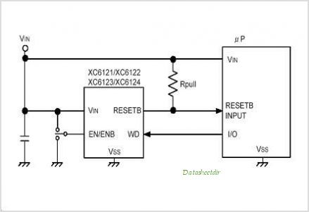
The XC61H series is a highly accurate, low power consumption CMOS voltage detector featuring a delay circuit. The detection voltage maintains high accuracy with minimal temperature drift. Output configurations are available in both CMOS and N-channel open drain. As...
The bat ultrasounds are picked up by the microphone SPKR1 and go through two stages of amplification at Q1 and Q2. Separately, a tunable (R12) single frequency is produced by the LM567 oscillator U1. The LM567 is a tone...
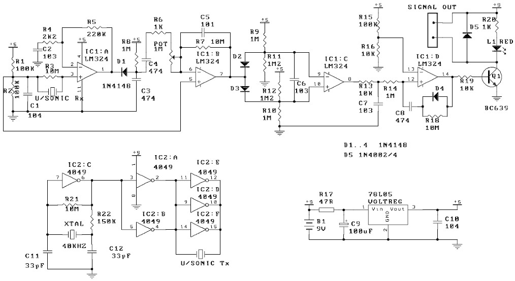
The circuit described exhibits high sensitivity to movement, capable of detecting even slight air movements such as hot air rising or wind blowing when the trimpot is adjusted to a sensitive position. The transmitter emits a continuous ultrasonic tone...
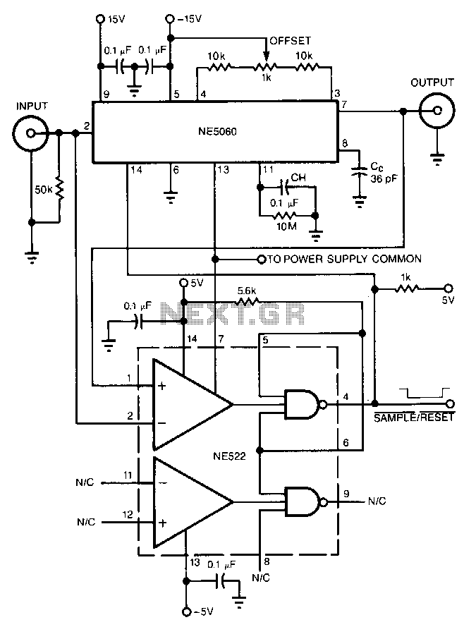
The high-speed peak detector utilizes a highly accurate, fast sample-and-hold (s/h) amplifier that is controlled by a high-speed comparator. The s/h amplifier retains the peak voltage until the comparator switches the amplifier to its sample mode to capture a...