
Ultrasound Detector with 567PLL and LM386 ICs
The circuit described involves several key components working together to process bat ultrasound signals. Initially, the microphone SPKR1 captures the high-frequency sounds emitted by bats. These sounds are then amplified through two transistor stages, Q1 and Q2, which enhance the signal strength for further processing.
The LM567 integrated circuit, designated as U1, operates as a voltage-controlled oscillator (VCO) in this configuration. Although the LM567 is primarily a tone decoder, grounding its input allows it to function as a precision oscillator. The frequency of oscillation is determined by the values of the capacitors and resistors in the circuit, specifically C4 and the combination of R10 and R12. The formula provided outlines how to calculate the frequency, indicating that it varies based on the resistance value of R12, which is tunable between 0 and 50 kΩ. This results in a frequency range of approximately 7.5 kHz to 88 kHz.
The mixing stage at transistor Q3 combines the amplified ultrasound signals from the microphone with the generated frequency from the LM567. This mixing process results in the production of signals that fall within the audio range, as well as higher frequencies. The ability to mix these signals allows for the detection and processing of bat calls, enabling further analysis or application in various electronic systems such as wildlife monitoring or research equipment.
Overall, the circuit demonstrates a sophisticated approach to audio signal processing, integrating amplification, oscillation, and mixing to effectively capture and utilize bat ultrasound signals.The bat ultrasounds are picked up by the microphone SPKR1 and go through two stages of amplification at Q1 and Q2. Separately, a tunable (R12) single frequency is produced by the LM567 oscillator U1. The LM567 is a tone decoder but here its input is grounded and its voltage controlled oscillator is used as a precision oscillator.
The oscillator frequency is given by f = 1/(1.1*C4*(R10 + R12)) = 1/(1.1*0.0022*10-6*(4.7 + [0-50])*103) = [88-7.5] khz The two signals are mixed at Q3 to produce both a signal in the audio range and higher frequencies that are the 🔗 External reference
Related Circuits
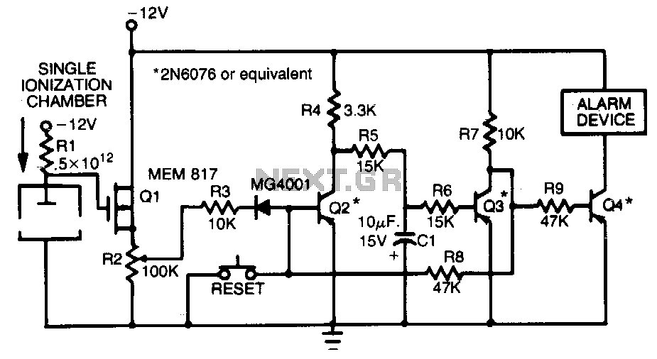
This smoke detector employs a MEM 817 p-channel enhancement mode MOSFET as its buffer amplifier. The sensor operates on the principle that the current decreases when smoke enters the chamber, leading to a negative voltage change at the gate...
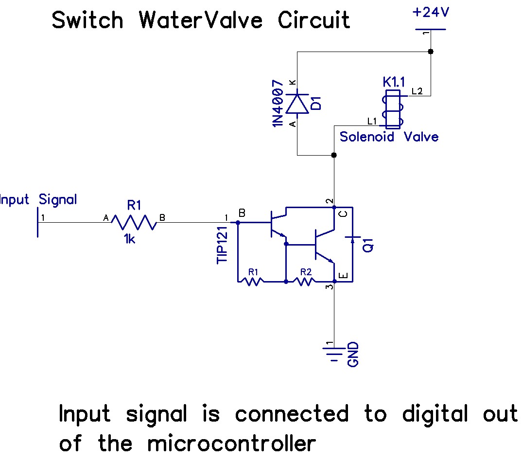
The Arduino Uno has adequate memory and ports, but efficient programming is necessary to store settings in memory. The Mega version offers increased memory and ports. The Shako valve operates on 24 volts DC; however, 12 volts is preferred...
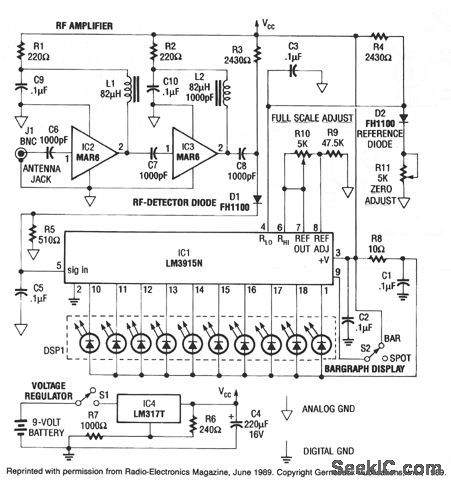
This RF detector can locate low-power transmitters (bugs) that are hidden from sight. It can sense the presence of a 1-mW transmitter at a distance of 20 feet, which is sensitive enough to detect the smallest bug. As the...
The integrated circuit LM386 is a low-power audio frequency amplifier that requires a low-level power supply, typically batteries. It is available in an 8-pin mini-DIP package. The IC is designed to provide a voltage amplification of 20 without the...
This is one of my favorites. The LM386 is a low voltage audio power amplifier. It can provide 125mW to 750mW, enough for any project that uses audio. This circuit can work with batteries, requires minimum external parts and...
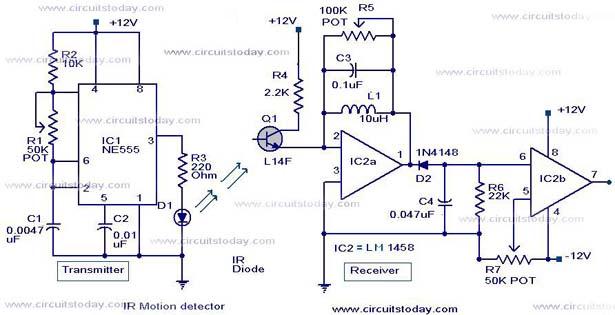
Infrared (IR) Motion Detector Circuit featuring a motion detector alarm and an infrared sensor. The circuit diagram and its operation are provided in detail. The infrared (IR) motion detector circuit is designed to detect motion within a specified range and...