
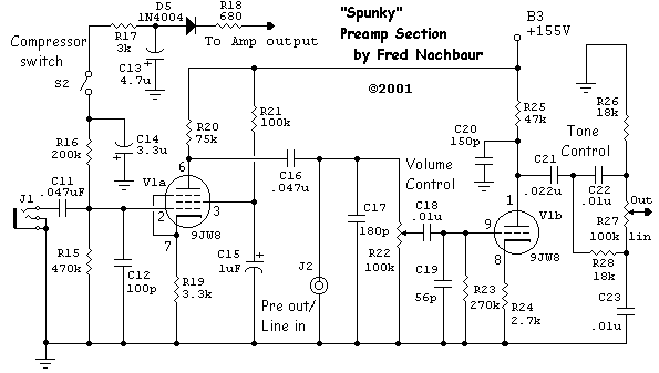
Spunky Tube Amplifier
The power supply circuit described employs a straightforward approach to achieve the necessary voltage and current for a low-power amplifier design. By utilizing the 120-volt AC line directly for filament power, the overall complexity and size of the transformer are reduced. The series-parallel arrangement of the filament circuitry ensures that the loss of one tube does not impact the operation of others, enhancing reliability. The dropping resistors, while generating heat, are well-managed through proper heat sinking, ensuring safe operation under load.
The B+ supply section is designed for efficiency and sufficient voltage headroom to accommodate varying signal conditions. The use of a full-wave rectifier and CRC filtering enhances the stability of the DC output, essential for maintaining consistent amplifier performance. The voltage-doubling circuit for bias generation is a clever solution that allows for variable bias control, a necessary feature in push-pull amplifier designs.
The inclusion of bypass capacitors at strategic points in the circuit reflects a thorough understanding of the potential issues associated with high-frequency response in guitar amplifiers. This attention to detail aids in minimizing unwanted noise and ensures that the amplifier operates within desirable frequency limits. Overall, this design exemplifies a practical and efficient approach to low-power amplifier construction, focusing on reliability, ease of maintenance, and sound quality.The diagram below shows that power supplies don`t have to be complicated, especially in low-power designs. The filaments are powered directly from the 120 volt AC line, minimising the size of the transformer(s) required to drive the amplifier.
Note the slightly unusual series-parallel arrangment; each pair of 35C5 output tube filaments is in series with one half of the 12AU7 dual triode. The center-tap of the 12AU7 sums the two branch currents (150 mA each) into the preamp tube, giving 300 mA as required for this valve`s heater supply. While unusual, this geometry is eminently stable and safe. If any tube is removed (or its filament burns out), none of the others will suffer as a result, unlike some series-wired television sets where a single burnout could take out several other tubes at the same time.
Each branch of two 35C5`s drops 70 volts. Add in the 6V drop across each half of the 12AU7, and the 9V drop across the 9JW8 input tube, and we have 85 volts. The two dropping resistors R1 and R2 each drop 36 volts (150 mA x 240 ohms = 36 V), for a nominal line input voltage of 121 volts.
Because of this dependance on 120 volt line voltage, this design is unfortunately not practical for 240 volt AC supplies. Incidentally, the two dropping resistors get quite hot during normal operation. I suggest cementing them to the chassis, and placing a small heat-sink on the other side to help dissipate the generated heat.
The heatsinks supplied with fans for 486 processors are perfect for this. (. just in case you wondered what the CPU heatsink was doing in the pictures!) The B+ supply is very conventional, consisting of a small plate transformer (150 volts either side of center-tap), a full-wave rectifier, and typical CRC filtering networks. The idea here is to get approximately 165-200 volts DC at the first filter output (B1) at quiescent current (about 80 mA), with enough headroom for full-signal conditions (about 125 mA).
At 165 volts, maximum output power will be on the order of 7 watts; at 200 volts you can expect as high as 9 watts. A small (12 volts at 100 to 300 mA) separate transformer is used to feed a voltage-doubler circuit, which supplies the four variable bias outputs for the finals.
The absence of regulation on either the B+ or bias lines is actually not a problem, since it in fact gives a certain degree of self-adjusting capability. If the power-line voltage sags, causing the B+ to decrease, the bias will also decrease, tending to increase the bias current and keep the plate dissipation relatively constant.
There`s nothing really surprising here, either. Each pair of tubes has its plates and screens tied together, but the control grids are brought out separately to allow independant bias adjustment. The output transformer is a Hammond 125C "universal" 8 watt push-pull device, that sounds surprisingly good considering its small size and relatively low cost.
Note that there are 4700 pF capacitors (C35, C36) at each plate junction to ground, i. e. effectively in parallel with the output. This is to limit high-frequency response. In guitar amplifiers, excessive high-frequency is a bane rather than a boon, since typical electric guitar signals will rarely have much content higher than a few kilohertz anyway. Leaving the bandwidth too wide only invites instability (due to cable runs, proximity to other gear, etc.
) and contributes to excessive hiss and other high-frequency artifacts. For this reason, you`ll find bypass capacitors at every stage in this design, as with other well-thought-out guitar amplifier designs. The 27 pF capacitors C30-C33 at the output valve grids are really not needed, but again I put them there as added insurance against ringing or outright oscillation.
They`re cheap, and can do no harm being there. As in th 🔗 External reference
Related Circuits
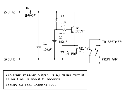
This is a simple circuit designed for an audio amplifier project to control the speaker output relay. The purpose of this circuit is to manage the delay that activates the relay, which connects the speakers to the audio amplifier....
Although the integrated circuit (IC) has largely replaced this circuit, the flexibility of the discrete device design still makes it practical. The components are readily available and cannot easily be eliminated. If desired, a small piece of metal can...
After restoring a Fisher 400, the search for another tube amplifier began, motivated by a desire to apply newly acquired skills. Importing equipment from the USA to the European Union proved costly, with shipping fees around $200 to $250,...
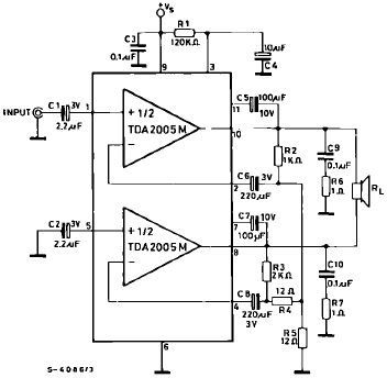
The TDA2005 is a Class B dual audio power amplifier package specifically designed for car radio applications. It facilitates the easy design of car radio power boosters. The TDA2005 power amplifier is engineered to deliver high-quality audio output in automotive...
Every electronic device that boosts electrical signals can be called an amplifier. The various amplifier types only differ in some specific features. Amplifiers are crucial components in electronic circuits, designed to increase the amplitude of electrical signals. They play a...
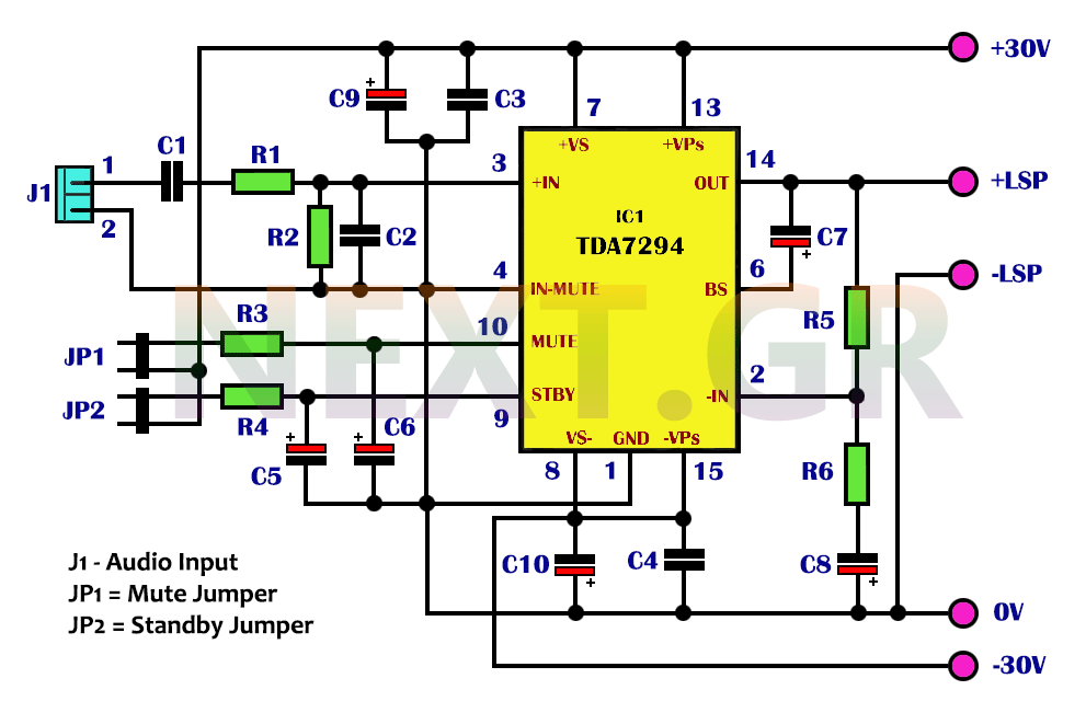
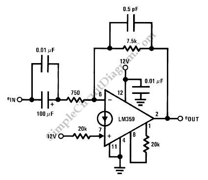
The integrated TDA7294 from SGS Thomson is a high-frequency acoustic power amplifier that boasts true high-precision specifications, making it suitable for various applications. Its standout feature is the significantly higher output power compared to typical amplifiers with similar distortion...