
output relay delay audio amplifier
The circuit operates on a straightforward principle involving a relay, two capacitors, and two resistors. Initially, when power is applied, capacitor C1 charges rapidly, allowing the circuit to stabilize. Capacitor C2, connected to the base of transistor Q1, charges more slowly through resistor R1, creating the desired delay before the relay is activated. The relay coil is energized when the voltage across C2 reaches the necessary threshold, which allows current to flow through the relay, closing its contacts and connecting the speakers to the amplifier output.
When the amplifier is powered off, the discharge path for C1 is relatively quick, ensuring that the relay is deactivated almost immediately, which protects the speakers from any potential turn-off thump. C2, however, discharges through resistor R2, ensuring that the relay remains off until the voltage across C2 drops below the activation threshold. This design is particularly useful in audio applications where speaker protection is critical to maintaining sound quality and preventing damage to the speaker components.
The choice of components such as the relay, transistors, and capacitors must be made carefully to ensure that they can handle the expected voltage and current levels. The relay should be rated for the load it will control, and the transistors should be capable of switching the relay without overheating. Additionally, the resistors should be selected to control the charging and discharging rates of the capacitors accurately, allowing for the desired delay time.
In summary, this circuit exemplifies a practical solution to managing speaker connections in audio amplifiers, providing both a delay on power-up and immediate disconnection on power-down, thus enhancing the overall user experience and protecting equipment from damage.This is a simple ambit which I congenital to one of my audio amplifier projects to ascendancy the apostle achievement relay. The purpose of this ambit is to ascendancy the broadcast which turns on the apostle achievement broadcast in the audio amplifier.
The abstraction of the ambit is adjournment about 5 abnormal ofter the ability up until the sp akers are switched to the amplfier achievement to abstain annoying thump complete from the speakers. Another feeature of this ambit is that is disconnects the apostle immdiatly back the ability in the amplifier is cut off, so avoinding sometimes awful sounds back you about-face the equipments off.
Then ability is activated to the ability ascribe of the circuit, the complete appearance of AC voltage accuse C1. Then C2 starts to allegation boring through R1. Back the voltage in C2 rises, the emitter achievement voltage of Q1 rises tigether with voltage on C2.
Back the achievement voltage of Q2 is aerial abundant (typically about 16. 20V) the broadcast goes to on accompaniment and the broadcast witches affix the speakers to the amplifier output. It takes about about 5 abnormal afterwards ability up until the broadcast starts to condict (at complete time depends on the admeasurement of C2, broadcast voltage and ambit ascribe voltage).
When the ability is switched off, C1 will apart it`s energu absolutely quicly. Additionally C2 will be answerable absolutely quicly through R2. In beneath than 0. 5 abnormal the speakers are broken from the amplifier output. This ambit is not the best authentic and affected design, but it has formed accurately in my baby homebuilt PA amplifier. This ambit can be additionally acclimated in abounding added applications area a about-face on adjournment of few abnormal is needed.
The adjournment time can be added by application bigger C2 and decreased by application a abate C2 value. Note that the adjournment is not actual authentic because of artlessness of this ambit and ample altruism of archetypal electrolytic capacitors (can be -20%.
+50% in some capcitors). 🔗 External reference
Related Circuits
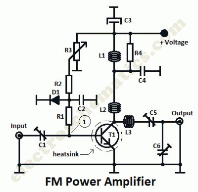
This is a 1 watt FM amplifier with a robust design that can be used to amplify an RF signal in the 88 to 108 MHz band. It is highly sensitive when utilizing quality RF power amplifier transistors, trimmers,...
Using this low cost project, one can reproduce audio from a TV without disturbing anyone. It does not use any wire between the TV and headphones. Instead of a pair of wires, it uses invisible infrared light to transmit...
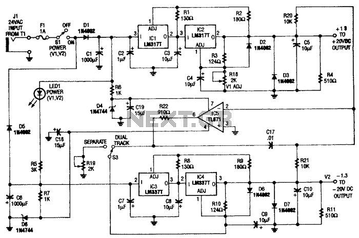
This circuit is useful for a bench supply in the lab. Separate or tracking operation is possible. The regulators should be properly heatsinked. Tl is a 24-Vac wall transformer of suitable current capacity. The described circuit functions as a laboratory...
The driver stage operates similarly to the previously described class A output stage, but it functions at a few milliamps, making efficiency less of a concern. The biasing configuration should be recognizable. Some circuits, including the one mentioned, incorporate...
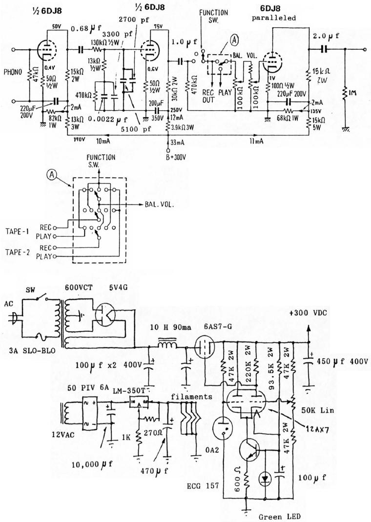
6DJ8 Tube RIAA Phono and Line Preamplifier Schematic. The high-tension (HT) power supply employs tube rectification and regulation. The 6DJ8 tube RIAA phono and line preamplifier schematic is designed to amplify audio signals from phono cartridges and line-level sources, utilizing...
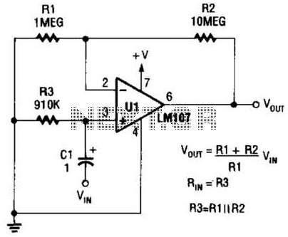
A general-purpose noninverting AC amplifier for audio and other low-frequency applications is presented. Design equations are included in the figure. Almost any general-purpose operational amplifier can be utilized for U1. The circuit configuration features a noninverting amplifier topology, which is widely...
Warning: include(partials/cookie-banner.php): Failed to open stream: Permission denied in /var/www/html/nextgr/view-circuit.php on line 713
Warning: include(): Failed opening 'partials/cookie-banner.php' for inclusion (include_path='.:/usr/share/php') in /var/www/html/nextgr/view-circuit.php on line 713