
50 Watt Hi-Fi power amplifier circuit
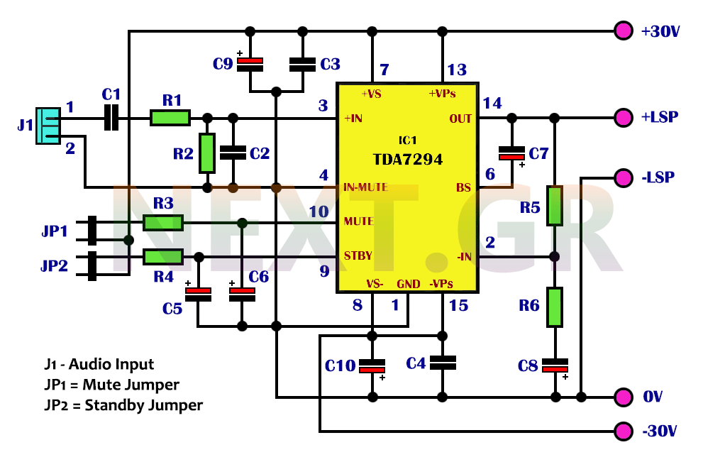
The TDA7294 circuit requires minimal external components. To maintain low overall distortion, the amplifier employs a significant amount of negative feedback, resulting in a closed-loop voltage gain of just 24dB. The input signal is connected to pin 3 via capacitor C1 and a low-pass filter formed by resistor R6 and capacitor C10, which helps reduce the risk of transient intermodulation distortion (TIM). Resistors R1 and R3 should be equal to minimize output voltage deviation, leading to an effective input resistance of approximately 10kΩ. The low cut-off frequency is set by the R1-C1 and R2-C2 networks at around 16 Hz, while the high cut-off frequency is approximately 100 kHz.
The amplifier can be muted with a positive voltage at pin 10 and placed in standby mode with a positive voltage at pin 9. It is essential to mute before switching the amplifier to standby. By connecting pins 9 and 10 directly to the power supply through resistors R5 and R4, the amplifier can be powered on automatically. To minimize noise during activation, the time constants of R4-C4 and R5-C5 can be adjusted, ensuring that the R4-C4 time constant is maintained.
The use of large smoothing capacitors in the power supply line may delay the amplifier's shutdown. If this is a concern, an external power supply detection network can be added, consisting of two rectifying diodes and small electrolytic capacitors that rectify the voltage from the secondary transformer. The PCB design can be simplified due to the minimal number of components. The metal surface of the integrated circuit connects internally to the negative power line, allowing the heatsink to be mounted directly on the PCB, which also carries a negative potential.
For thermal management, the heatsink size should be chosen based on a continuous output power of 50W at 8Ω. The same heatsink can adequately handle music power of 80W at 4Ω. The integrated circuit is designed to fuse at 145°C and can tolerate temperatures up to 150°C, minimizing thermal issues. The load connection to the board is made using three screw terminals, ensuring a robust electrical connection. For symmetric power supply, it is recommended to use a toroidal transformer, a 25A bridge rectifier, and two 10,000μF electrolytic capacitors rated for 50V.
The TDA7294 is well-suited for high-fidelity applications, and its compact size allows it to be used with a preamplifier or integrated into a loudspeaker to create a compact audio solution. Measured distortion levels, assessed using a spectrum analyzer, show that at 40W and 8Ω with an 80kHz bandwidth, distortion increases at high frequencies but remains below 0.04%. At low frequencies up to approximately 1 kHz, total harmonic distortion (THD + N) is below 0.002%, indicating exceptional performance under stringent conditions.
The key specifications include:
- Input sensitivity: 1.3V (50W, 8Ω)
- Input impedance: 10kΩ
- Bandwidth: 16Hz to 100kHz
- Output voltage rise rate: 10V/μs
- Output power: 50W at 8Ω, 0.1% THD / 82W at 4Ω, 0.1% THD
- Signal-to-noise ratio: 105dBa (1W, 8Ω)
- THD + N at 40W and 8Ω: 0.002% (1kHz) / <0.04% (20Hz-20kHz)
After connecting the circuit with an audio signal generator, heatsink, power supply at +/- 30V, and speaker output, the amplifier should produce a loud sound, confirming its operation. Disconnecting the speaker terminals and connecting them to an oscilloscope allows for detailed observation of the output signal. For a 1kHz input signal, the circuit performs well up to 4Vpp, producing a 6Vpp output signal. However, at 5Vpp input and beyond, clipping may occur. There should be no phase distortion from 100Hz to 80kHz at input levels up to 5Vpp.
In conclusion, the TDA7294 serves as an effective 50W amplifier with a single integrated circuit, delivering excellent performance without amplitude, phase, or frequency distortion across a bandwidth of 10Hz to 80kHz, affirming its suitability for high-fidelity acoustic applications.
List of Components:
- R1 = 150Ω
- R2, R3, R5 = 10KΩ
- R4 = 22KΩ
- R6 = 680KΩ
- C1 = 1.5nF / 63V Metallised Polyester
- C2 = 2.7nF
- C3, C4 = 100nF
- C5, C6 = 10μF / 63V Electrolytic
- C7, C8 = 22μF / 63V Electrolytic
- C9, C10 = 2200μF / 25V Electrolytic
- IC1 = TDA7294
- HeatsinkSGS Thomson's integrated TDA7294 is a high-frequency acoustic power amplifier, with true high-precision specifications, suited for all relevant applications. Its main feature is much higher output power than is usual in amplifiers with similar distortion performance.
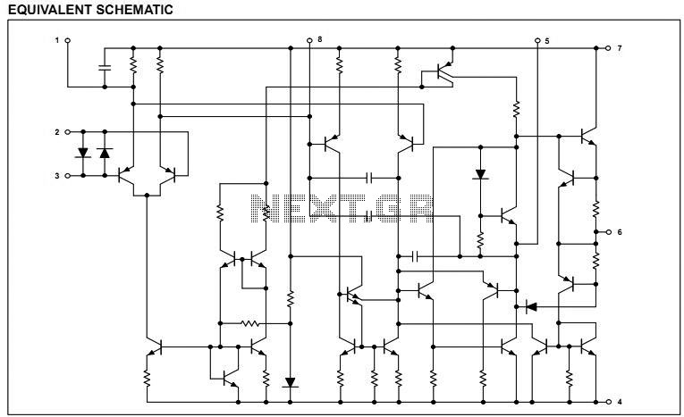
According to its manufacturer, the output stage of this 15-pin integrated can give up to 100W. From the summary specifications listed above, plus the fact that the TDA7294 has reliable protection against short-circuiting the output and overheating, we conclude that it is remarkably complete. It should be noted, however, that the output power of 100W is rather excessive because it refers to the IEC output musical power, under 10% harmonic distortion, which of course is not the correct way to determine the output power for Hi-Fi.
Besides, with balanced +/-40V supply and 4Ω load resistance, the integrated can overheat very quickly. For this purpose, the supply voltage is kept at the safest value of +/-30V, where it is effortlessly delivered 50W at 8Ω and 80W at 4Ω.
These values are not insignificant, taking into account the reasonable disposal value of TDA7294.
The TDA7294 circuit requires minimal external components. In order to keep the overall distortion low, the amplifier operates with a large percentage of negative feedback, with a gain of closed loop voltage of just 24dB.
The input signal is applied to pin 3 via C1 and the low pass filter R6-C10 that minimizes the risk of TIM degradation. R1 and R3 must be equal to minimize output voltage deflection, so the input resistance is practically equal to 10kΩ in our circuit.
The low cut-off frequency is determined by the R1-C1 and R2-C2 lattices at approximately 16 Hz. The high cut-off frequency is about 100 KHz.
The amplifier can be mute with a positive voltage at pin 10 and put on hold with a positive voltage at pin 9. The squelch must always be done before the amplifier is switched to standby. By connecting these pins (9 and 10) permanently to the power supply via the resistors R5 and R4, we energize the amplifier as soon as it is energized.
To avoid some noise during activation, the time constants R4-C4 and R5-C5 can be increased by always maintaining the R4-C4 time constant.
The (forced) use of large smoothing capacitors in the feed line causes delay in switching off the amplifier. If this is considered a drawback, you can add an external power supply detection network. This could be two rectifying diodes with two small electrolytes that will rectify the voltage of the secondary power transformer.
The plaque has been predicted as additional welding pins near the squelch and standby inputs. Secondary positive voltage can be used to quickly control these inputs when the amplifier is turned off.
Because of the few components, the PCB can be designed very easy. The metal surface of the integrated communicates internally with the negative feed line, so to save the use of mica between the heatsink and the TDA7294 (but the silicone paste is needed), the heatsink is placed on the PCB and, of course, has the negative potential.
To choose the size of the heatsink we assumed a continuous output power of 50W at 8Ω.
The same heatsink is enough for a music power of 80W at 4Ω. Thermal problems are unlikely to have, since the completed is automatically fused to 145°C and is waiting for 150°C.
The connection of the load to the board is made with three screwed wire contacts, which ensure a very good electrical connection. For symmetric feed, it is better to use a toroidal transformer, bridge 25A and two 10000μF electrolytic cells at 50V.
The TDA7294 is suitable for any high-fidelity application.
Its small volume allows its use with a preamplifier or its integration into a loudspeaker to create a compact loudspeaker.
The measured deformation of the amplifier, as measured by the use of a spectrum analyzer, with 40 W at 8Ω and 80kHz bandwidth, climbs at high frequencies but does not exceed 0.04%. From low frequencies up to about 1 kHz, total harmonic distortion (THD + N) is below 0.002%, indicating excellent performance under the strictest requirements.
- Input sensitivity = 1.3V (50W, 8Ω)
- 10KΩ input impedance
- Bandwidth = 16Hz-100kHz
- Output voltage rise rate = 10V/μS
- Output voltage rise rate = 10V/μS
- Output power = 50W, 8Ω, 0.1% THD / 82W, 4Ω, 0.1% THD
- Signal to Noise Ratio = 105dBa, (1W, 8Ω)
- THD+N with 40W at 8Ω = 0.002% (1kHz) / <0.04% (20Hz-20kHz)
Measurements
After you properly and carefully have connected your circuit with a audio signal generator, the heatsink on board, the power supply at +/- 30V and the speaker at the output, you will heard a deafening sound coming out of the speaker so the amplifier works and works properly.
Then remove the terminals from the speaker and connect them to an oscilloscope for a more supervised study of the circuit. For the given input signal you should have a good output signal.
The signal of 1KHz from the frequency generator (average acoustic tone frequency) and by changing the input width you will notice that up to 4Vpp the circuit works perfectly with a 6Vpp output signal. While at 5 Vpp input and beyond you will observe clipping at the output voltage. Also there shouldn't be any phase distortion in the range from 100Hz to 80kHz and up to 5Vpp.
Conclusions
According to the specifications of the 50W final amplifier with a single IC you get:
Practically a very good power amplifier that works perfectly up to 4Vpp inputs without amplitude, phase, frequency deformations and operates in the bandwidth of frequencies from 10Hz to 80kHz, ie in the audio frequency range. So this circuit is indeed a high-fidelity acoustic power amplifier, to be used in any Hi-Fi application.
List of Components
- R1 = 150Ω
- R2, R3, R5 = 10KΩ
- R4 = 22KΩ
- R6 = 680KΩ
- C1 = 1.5nF / 63V Metallised Polyester
- C2 = 2.7nF
- C3, C4 = 100nF
- C5, C6 = 10μF / 63V Electrolytic
- C7, C8 = 22μF / 63V Electrolytic
- C9, C10 = 2200μF / 25V Electrolytic
- IC1 = TDA7294
- Heatsink
Related Circuits
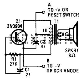
This is a simple low-level noise maker that is ideally suited for certain alarm applications. When the sounder is located in another part of the building, the sound level is loud enough to be heard but is not loud...
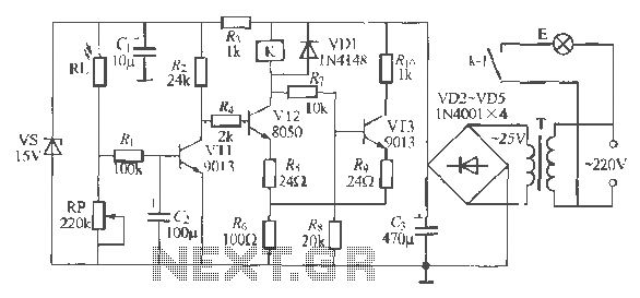
The circuit operates as a light-activated switch that controls white moving lights. It features high sensitivity, stable performance, and good anti-interference characteristics. A photosensitive resistor (RI) is employed to detect ambient light levels. During the day, the resistor exhibits...
NE5532DR absolute maximum ratings: (1) Supply voltage: VCC+ 22 V; VCC-: -22 V; (2) Input voltage, either input VCC ±; (3) Input current: ±10 mA; (4) Duration of output short circuit: Unlimited; (5) Package thermal impedance, JA: D package...
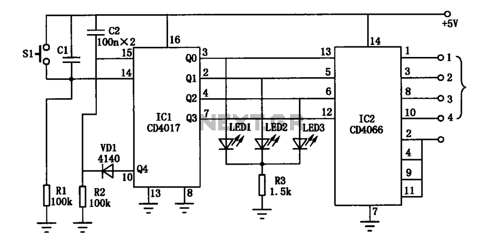
The electronic circuit diagram consists of the CD4017 and CD4066 components configured as a switch circuit. The CD4017 is a decade counter integrated circuit (IC) that can drive up to ten outputs, sequentially activating them based on clock pulses. It...
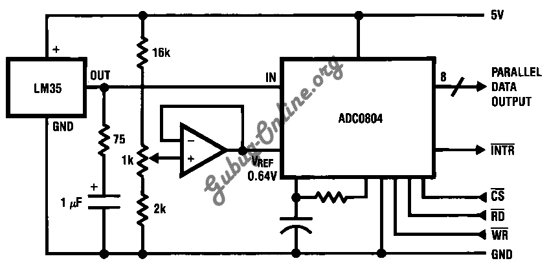
This is a design for a temperature-to-digital converter circuit that is controlled by the LM35 integrated circuit. The LM35 is a precision integrated circuit temperature sensor, whose output voltage is linearly proportional to the Celsius temperature. The circuit utilizes the...
This precise one-pulse-per-second clock is constructed using a few common components and is driven by a 50 or 60 Hertz mains supply without a direct connection to it. An audible beep or a metronome-like click, along with a visible...
Warning: include(partials/cookie-banner.php): Failed to open stream: Permission denied in /var/www/html/nextgr/view-circuit.php on line 713
Warning: include(): Failed opening 'partials/cookie-banner.php' for inclusion (include_path='.:/usr/share/php') in /var/www/html/nextgr/view-circuit.php on line 713