
Spy Phone Bug Transmitter Circuit
This telephone broadcasting circuit employs a simple yet effective design to enable eavesdropping on conversations. The automatic switching mechanism integrates various components, ensuring low power consumption while maintaining functionality. The use of a voltage divider formed by resistors R1 and VR1 is critical for controlling the operational state of the transistors. The zener diode plays a pivotal role in regulating the switching voltage, allowing for precise control over the circuit's activation and deactivation based on the telephone line's voltage.
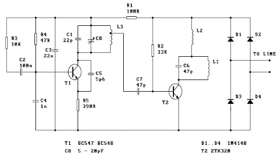
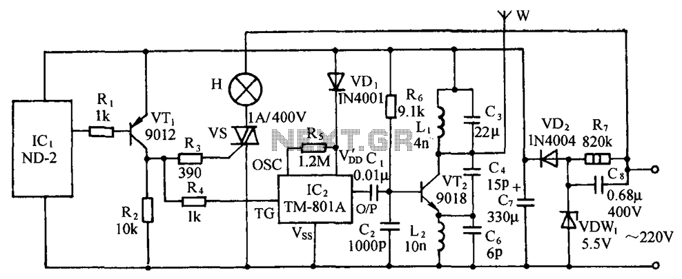
In the FM transmitter section, the common-emitter configuration of transistor T3 allows for efficient modulation of the RF signal, which is essential for transmitting audio signals over a distance. The inclusion of coil L1 aids in establishing the oscillation frequency, further enhancing the circuit's performance. The circuit's compact design enables it to be discreetly integrated into existing telephone infrastructure, making it a practical solution for wireless amplification and monitoring of telephone conversations. The overall design emphasizes efficiency, low power usage, and ease of installation, making it suitable for various applications in telecommunications and audio transmission.A very simple telephone broadcaster or transmitter which can be used to eavesdrop on a telephone conversation. The circuit can also be used as a wireless telephone amplifier. One important feature of this phone transmitter is that the circuit derives its power directly from the active telephone lines, and thus avoids use of any external ba
ttery or other power supplies. This not only saves a lot of space but also money. It consumes very low current from telephone lines without disturbing its performance. The phone bug transmitter is very tiny and can be built using a single -IC type veroboard that can be easily fitted inside a telephone connectin box of 3. 75cm x 5cm. Automatic switching section comprises resistors R1 to R3, preset VR1, transistor T1 and T2, zener D2 and diode D1.
Resistor R1, along with preset VR1, works as a voltage divider. When voltage across the telephone lines is 48V DC, the voltage available at wiper of preset VR1 ranges from 0 to 32V (adjustable). The switching voltage of the circuit depends on zener breakdown voltage and switching voltage of the transistor T1.
Thus, if we adjust preset VR1 to get over 24. 7 volts, it will cause the zener to breakdown and transistor T1 to conduc. As a result collector of transistor T1 will get pulled towards negative supply, to cut off transistor T2. At this stage, if you lift the handset of the telephone, the line voltage drops to about 11V and transistor T1 is cut off.
As a result, T2 gets forward biased through R2 to provide a DC path for T3 used in the following FM transmitter section. The low-power FM transmitter section comprises oscillator transistor T3, coil L1 and a few other components.
T3 works as a common-emitter RF oscillator, with T2 serving as an electronic on/off switch. The audio signal available across the telephone lines automatically modulates oscillator frequency via T2 along with its biasing R3. The modulated RF signal is fed to the antenna. The telephne conversation can be heard on an FM receiver remotely when it is tuned to the transmitter frequency.
🔗 External reference
Related Circuits
Obtain more information about the circuit diagram of a mobile jammer by visiting this link. A GSM jammer, or cell phone jammer, is a device that transmits signals on the same frequency used by the GSM system. The effectiveness...
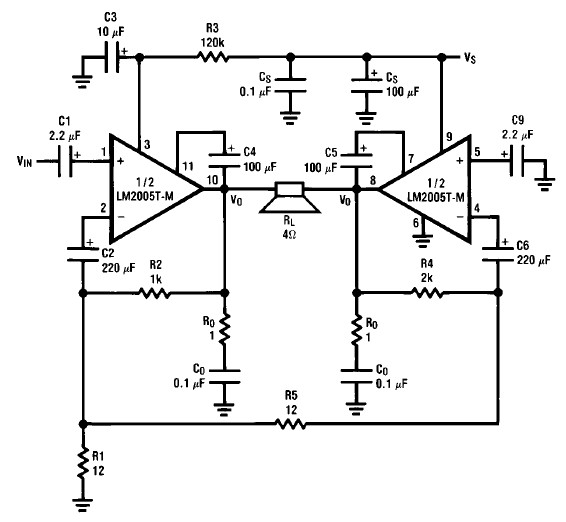
A simple 20-watt amplifier electronic project can be designed using the LM2005 dual high-power amplifier, which is engineered to provide optimal performance and reliability for automotive applications. The LM2005 20-watt amplifier has a high current capability of 3.5A, allowing...
The primary issue with the design of a stereo amplifier that includes a total bass driver is that the signals from the left and right channels eventually become combined. This summation process minimizes the separation between channels, compromising the...
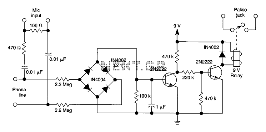
The DC voltage present on the telephone line typically ranges from 45 to 50V when on-hook and drops to approximately 6V when off-hook. This condition activates a step-down circuit relay, which in turn controls a tape recorder. Audio input...

The ISO100 multichannel data acquisition system comprises a programmable gain amplifier isolated by an optocoupler, a programmable amplifier (PGA100), and an isolation amplifier (ISO100). The optocoupler selects three channels and is coupled to the programmable gain amplifier, which can...
The circuit includes a comprehensive array of components such as vibration sensors, a follower, a lamp relay control circuit, a voice sounding circuit, a high-frequency oscillation circuit, and an AC rectifier buck power supply circuit. The vibration sensor is...