
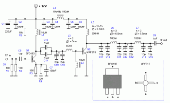
Circuit Diagram of Mobile Jammer
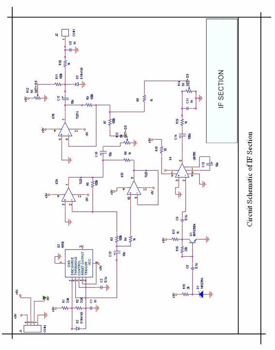
A GSM jammer functions by emitting radio frequency signals that interfere with the communication between mobile devices and cell towers. Typically, these devices operate within the frequency range of 900 MHz to 1800 MHz, which encompasses the frequencies used by most GSM networks. The jammer's transmitter generates a continuous wave signal that overwhelms the legitimate signals from the cell towers, effectively creating a noise floor that mobile devices cannot penetrate.
The circuit design of a GSM jammer generally includes several key components: a signal generator, power amplifier, and antennas. The signal generator creates the jamming signal, which can be adjusted to match the specific frequency of the target GSM network. The power amplifier boosts the signal strength to ensure effective coverage over the desired area. Antennas are used to radiate the jamming signal, with designs that may vary based on the intended range and directionality of the jamming effect.
Power supply circuitry is also critical, as the jammer requires a stable power source to operate efficiently. Additionally, safety precautions must be considered, as the use of jammers is heavily regulated in many jurisdictions due to their potential to disrupt emergency communications and other essential services.
In summary, while GSM jammers can effectively disable mobile communications within their range, their deployment is subject to legal restrictions, and they should be used with caution, adhering to applicable regulations.Get More Information about Circuit Diagram of Mobile Jammer by visiting this link.A GSM Jammer or cell phone jammer is a device that transmit signal on the same frequency at which the GSM system operates, the jamming success when the mobile phones in the area where the jammer is located are disabled.. 🔗 External reference
Related Circuits

This circuit is a robust and efficient power amplifier suitable for various audio applications. It delivers 60W RMS output at a 50V supply with an 8 Ohm load. The design is user-friendly, allowing for the use of non-critical components...
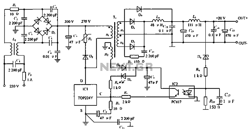
The circuit depicted in the figure is designed to achieve a higher power output by modifying specific components. On the left side of the figure, components R1, L1, D1, and capacitors C1 to C7 form a conventional filtering and...
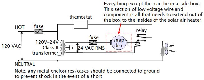
For various experiments, such as solar air heaters, an automatic fan activation and deactivation system is required. A straightforward solution is to use a bimetal snap disc thermal sensor. This sensor functions as a switch that closes when a...
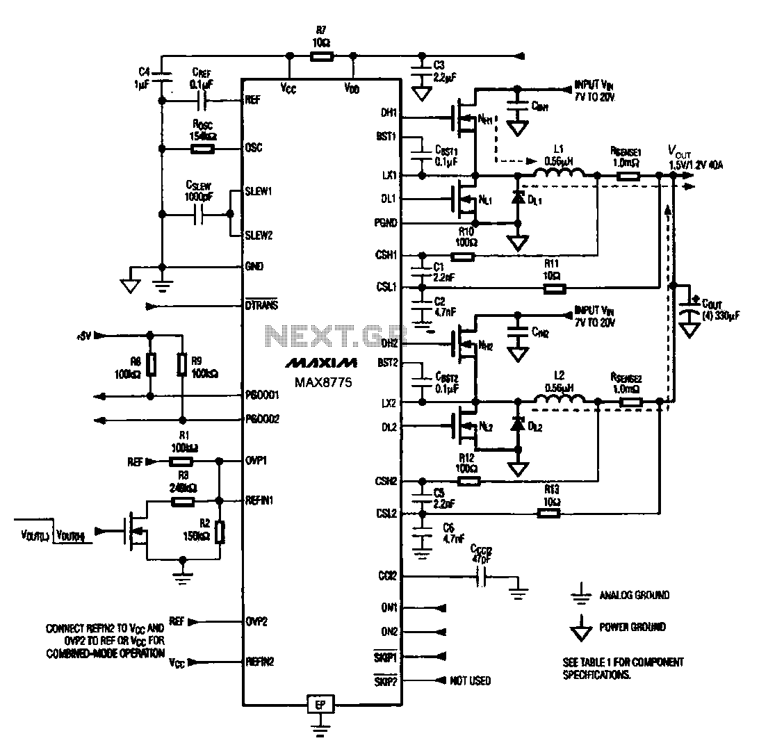
Notebook computer chip power supply circuit, which generates the PWM circuit using MAX8775. The notebook computer chip power supply circuit utilizes the MAX8775 integrated circuit to generate a Pulse Width Modulation (PWM) signal. The MAX8775 is a high-efficiency step-down voltage...

This series-feedback configuration of components provides a high input impedance and stable, wide-band gain video amplifier suitable for general-purpose applications. Below is the schematic representation of the circuit. The described video amplifier circuit employs a series-feedback topology, which is instrumental...
An RF power amplifier is a type of electronic amplifier used to convert a low-power radio-frequency signal into a larger signal of significant power, typically for driving the antenna of a transmitter. It is optimized for high efficiency, high...