
Square Wave Generator

The proposed function generator circuit will utilize a transistor-based architecture to generate a variety of waveform outputs, including sine, triangle, and square waves. The primary components will include transistors, resistors, capacitors, and a voltage regulator, with careful consideration given to the selection of transistors to ensure compatibility and performance. The circuit will be designed to accommodate dual frequency bands, enabling operation across a broad range of frequencies.
For sine wave generation, a Wien-bridge oscillator configuration will be implemented, utilizing feedback mechanisms to maintain stability and minimize distortion. The gain will be carefully adjusted using a combination of fixed resistors and variable components to ensure optimal performance. The use of a lightbulb in the circuit will facilitate dynamic gain control, allowing for gradual adjustments as the oscillator stabilizes.
In addition to the Wien-bridge oscillator, a square wave output will be generated using an astable multivibrator configuration. This will ensure that square waveforms are produced consistently and reliably, with the ability to adjust the frequency through the selection of timing components.
The incorporation of dual-ganged variable resistors will enable fine-tuning of the frequency output, while the option to use standard potentiometers will provide flexibility in component sourcing. The overall design will prioritize simplicity and reliability, ensuring that the function generator can be constructed with readily available components while delivering high performance across its intended frequency range.
The circuit layout will be carefully designed to minimize noise and interference, with adequate decoupling and bypass capacitors employed to maintain signal integrity. The final implementation will be tested rigorously to confirm that the frequency stability and waveform quality meet the desired specifications, ensuring that the function generator serves its intended purpose effectively in both lab and field applications.One is in good shape, made in 1979, and capable of producing sine, triangle and square waveforms. This one is retained and used as main function generator for testing purposes at my main office location. Other three were not working, or working sporadically. They were all from 1950-ies or early 1960-ies, with electron tubes, of two different types. High voltage was ok on all of them, but output was lacking or intermittent. I decided to scrap them, keep the working tubes, transformers and metal for future projects, and make a new function generator using only transistors. This new generator will be used in the machine shop location. New generator was supposed to have all the bells and whistles, and use case and if possible other parts from the scrapped vacuum-tube generators.
Transistor-only design might seem strange at this day and age. However, I wanted to challenge myself. And there was another, somewhat nostalgic reason: I have spent some years in a war zone, and I can appreciate how difficult it is to extract chips from boards (and get their datasheets) during times of war. Transistors were easily removed from equipment, and were not critical when in different role. BC108 will work just as well as 2N2222 in a LF amplifier for instance - often without any change in external components.
Therefore, transistor design has a practical second and third world use, IC based one much less so. No special chip Tough luck. It`s not going to arrive on a mortar round. So, for all the people in the world that are maybe now in the similar situation that I was some 20 years ago, it is going to be a simple and reliable, no frills build. Use of a voltage regulator IC is not cheating. Device works perfectly well without it, frequency is just more stable with regulator. Frequency drift using unregulated power supply is only 2-3 %. Frequency drift with 5 V voltage regulator, measured in a 24 hour run, is always less than 1%. And anyway, 78L05 is a three terminal device :) Complaint that`s more to the point is the dual rotary switch with 5 positions.
If you can`t find it, you can use regular DPDT switch for two bands only. Bands can be "streched" by using smaller band shortening fixed resistors (1 Kiloohm in my schematic). This will increase total ratio of resistance change and provide wider range (and coarser) tuning. Other option is to use Megaohm dual-ganged base variable resistors with Darlingtons instead of regular transistors (see here, Figure 14).
With those measures, it is possible to achieve say 10 Hz - 1 KHz band A and 1 KHz - 100 KHz band B. No DPDT switch / just lazy you say Use one band only and you don`t need a switch at all. You have no dual-ganged variable resistors Ok, just find two regular potentiometers. Your tunning will now involve adjusting 2 pots, but that is a small price to pay for a working function generator, if nothing else is available. For several weeks, when time permitted, I was testing different configurations of sine and square-wave oscillators.
They all had some advantages and shortcomings. Very good overview page: Wien-bridge oscillator: I tried two different transistor based designs and they only worked well in narrow range, and there was a number of other problems. Gain had to be set to little above 3 initially and then lowered to 3 for least amount of distortion. A small lightbulb was often used in the past to provide changing resistance for gradual gain reduction.
Resistance of the bulb would increase after the power is applied, decreasing positive feedback and gain. LC oscillators: really hard to use at lower frequencies. And your 500 picofarad variable cap is not going to change much of a frequency when connected to a large 100 mH coil.
So a variable coil is needed. LC oscillators are excellent for radio range though. Astable multivibrator : produces square waves and pulses, easy to get to work, stable and works with wide variety of voltage s 🔗 External reference
Related Circuits
The current design of a power inverter offers an efficiency of approximately 85% and a power output exceeding 200 watts. This document provides a complete circuit schematic and detailed building procedure for a home-built power inverter. While numerous articles...
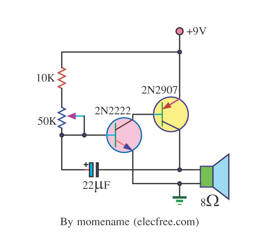
This is a simple tone oscillator generator. It uses the transistors 2N2222 and 2N2907 as the main components. The tone sound is controlled with a 50K ohm resistor (R2) and an 8-ohm speaker is utilized. The tone oscillator generator circuit...
Frequencies that exceed the limits of human hearing are referred to as ultrasonic waves or frequencies. These ultrasonic waves can be generated using various components, including piezoelectric cells, magnetostrictive oscillators, piezoelectric oscillators, and Hartley oscillators with piezoelectric cells. Ultrasonic waves...
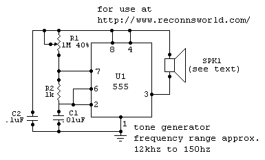
this tone generator can be used to control your robot. you will need to use the tone decoder for this. to widen the range, higher or lower - substitute a higher, or lower valued capacitor for c1. for frequencies...
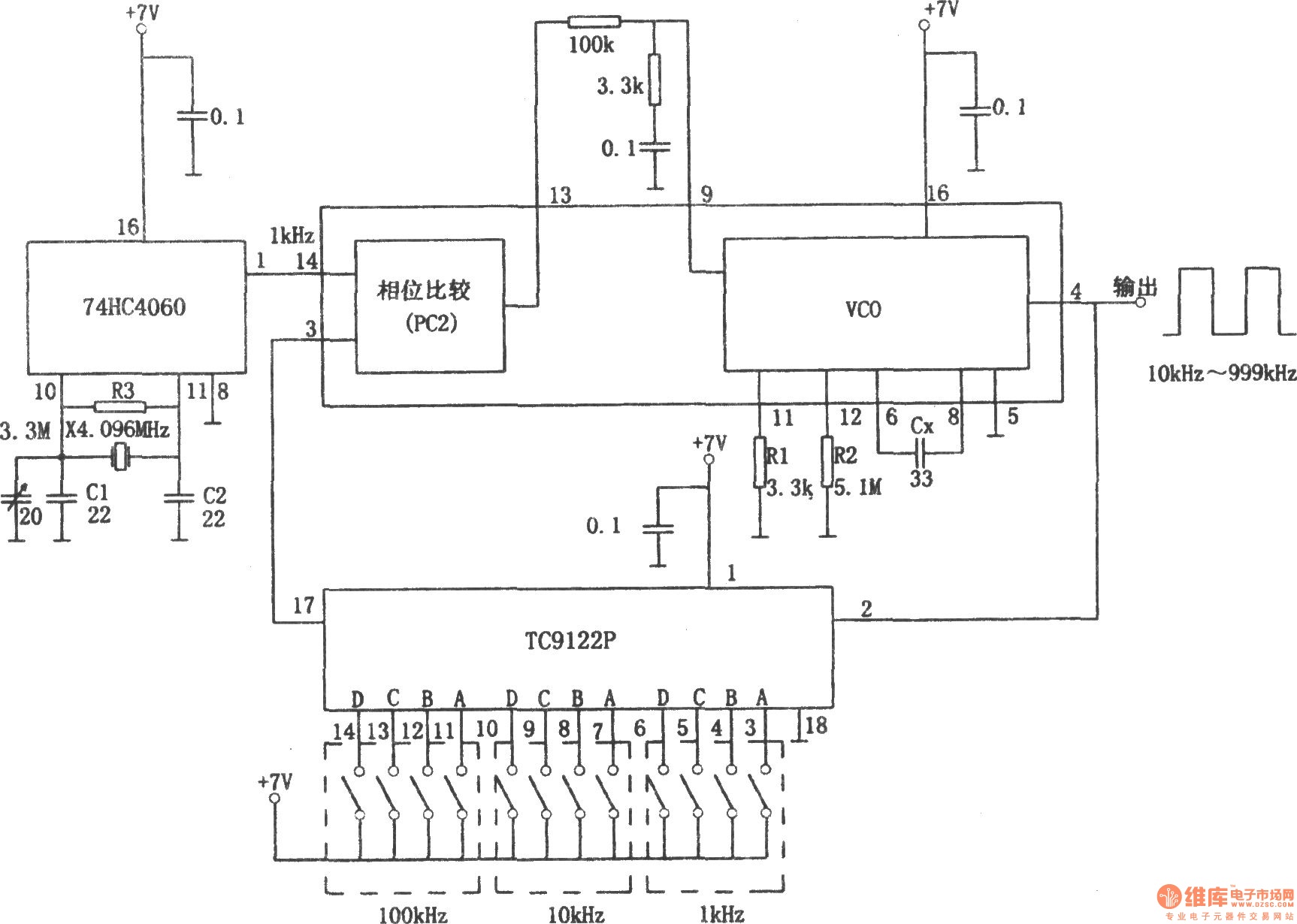
The PLL pulse generator is illustrated in the accompanying chart. The circuit represents a phase-locked loop (PLL) pulse generator. The PLL generates a fractional frequency from a crystal oscillator, producing a 1 kHz stepped frequency signal. Additionally, it outputs...
Let's face it, not every day is the greatest. Sometimes, one may not feel like doing much of anything. Wouldn't it be nice if there was a way to change brain waves at the push of a button? Transcranial...