
PLL pulse generator(74HC4060 TC9122P)
")
The PLL pulse generator circuit utilizes a phase-locked loop architecture to achieve precise frequency control and stability. The 74HC4060 integrated circuit serves as the core of this design, integrating multiple functions including a NOT gate and a binary frequency divider. The NOT gate is essential for generating the necessary phase relationship with the crystal oscillator, which operates at a frequency of 4.096 MHz. This oscillator is crucial for establishing a stable reference signal, which is subsequently divided down to a 1 kHz output through the frequency divider.
The TC9122P programmable counter enhances the circuit's flexibility by allowing for programmable division ratios. The BCD code programming enables the selection of division ratios from a minimum of 8 up to a maximum of 999, thus accommodating a wide range of applications. The operational range between division ratios of 10 and 999 ensures that the circuit can provide various output frequencies tailored to specific needs.
Phase comparison is a critical function of the PLL, with the 74HC4060 offering three types of phase comparators. Phase comparator PC2 is particularly noteworthy as it compares the output frequency of the circuit with the positive edge of the reference frequency, facilitating effective feedback for maintaining synchronization. This feedback loop is essential for the stability of the PLL operation.
The voltage-controlled oscillator (VCO) within this circuit is influenced by external components Cx, R1, and R2. These components determine the oscillation frequency of the VCO, allowing for further tuning of the output frequency to meet specific requirements. The design of this PLL pulse generator circuit exemplifies a sophisticated approach to frequency generation, combining various elements to achieve precise control and versatility in output waveform characteristics.The PLL pulse generator is shown as the chart. The circuit is the phase-locked loop (PLL) pulse generator circuit. PLL makes a fractional frequency to crystal oscillator and gets 1kHz stepped frequency signal, moreover, it obtains 10kHz 999kHz pulse waveform on the output terminal. The manifold block 74HC4060 is a type of integrated chip with NOT gate and 1/2n frequency dividing circuit inside, among them, the NOT gate and the crystal oscillator with 4. 096MHz form a oscillator circuit, and the frequency dividing circuit gets lkHz reference frequency signal by it.
TC9122P is a high-speed programmable counter and its dividing ratio is decided by the BCD code, the programming data make the frequency ratio range be in 8 to 999, the circuit operates under the dividing ratio between 10 and 999. There are 3 types of phase comparator in 74HC4060, and the phase comparator PC2 can compare the output frequency with the positive edge of reference frequency, and get their feedback.
The oscillation frequency of VC0 is decided by Cx, R1 and R2. 🔗 External reference
Related Circuits
Devices capable of disabling and destroying microorganisms such as viruses, bacteria, and fungi through the application of a pulsed, intense magnetic field are not futuristic concepts but are currently available. Several pulsed magnetic field instruments are already in use...
At half brightness, the lamp current is pulsed on and off by the voltage developed across the resistor and capacitor at the current-sense output. The current-sense output detects the lamp current. A basic pulse-width modulation (PWM) lamp-brightness control circuit...

The circuit below demonstrates the generation of a single positive pulse that is delayed in relation to the trigger input time. It is similar to a previously described circuit but utilizes two stages, allowing for control over both the...
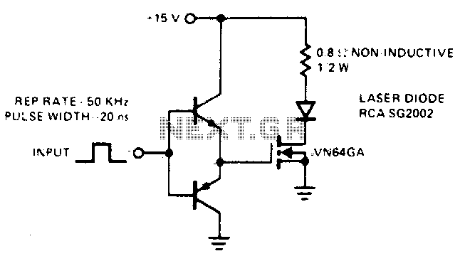
This drive is capable of supplying the laser diode with 10 ampere pulses lasting 20 ns. With a 0% duty cycle, the repetition rate is 50 kHz. A complementary emitter-follower configuration is utilized as a driver. Switching speed is...
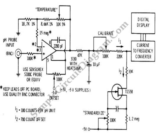
A signal conditioner for a pH meter probe requires high input impedance. The signal conditioning of the pH meter probe is achieved by incorporating a buffer. The design of a signal conditioner for a pH meter probe is critical for...
IC1 generates a pulse that modulates the 1000-Hz tone generated by IC2. This circuit can be used to generate warning or alert signals. The circuit described consists of two integrated circuits (ICs), where IC1 is responsible for generating a pulse...