
Square Wave Generator using Op-Amp
The op-amp relaxation oscillator circuit is characterized by its simplicity and effectiveness in generating square waveforms. The circuit's operation hinges on the interplay between the charging and discharging of the capacitor and the feedback mechanism provided by the op-amp comparator. The choice of component values, particularly the resistance of R_f and the capacitance of C, directly influences the frequency and duty cycle of the output waveform. The Zener diodes serve a critical role in clamping the output voltage, ensuring that the op-amp operates within safe limits while allowing the generation of the desired waveform.
The design of this oscillator can be tailored to specific applications by adjusting the values of R_f and C, thus altering the time constants involved in the charging and discharging processes. This flexibility enables the generation of square waves with varying frequencies, making the circuit suitable for a wide range of applications, including clock signals for digital circuits, tone generation in audio applications, and signal modulation.
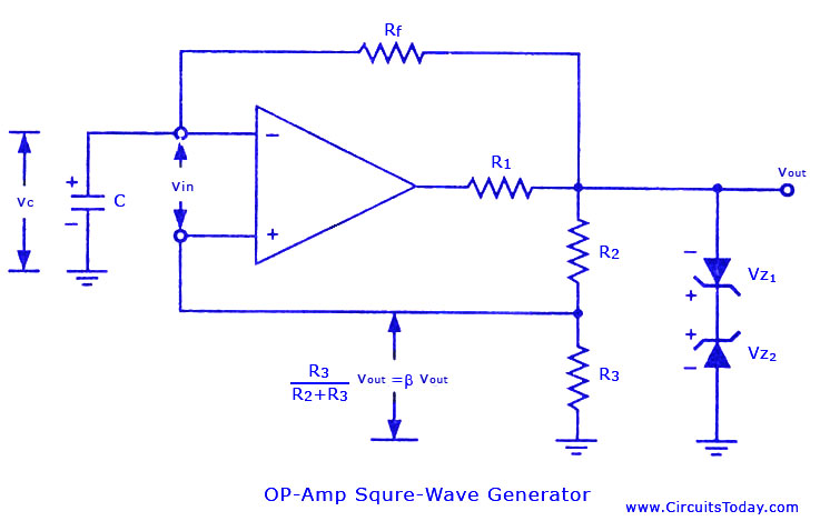
In summary, the op-amp relaxation oscillator is a versatile and valuable circuit for generating square waveforms efficiently, with its performance dictated by the careful selection of components and configuration. This circuit exemplifies the principles of feedback and oscillation, showcasing the capabilities of operational amplifiers in waveform generation.The non-sinusoidal waveform generators are also called relaxation oscillators. The op-amp relaxation oscillator shown in figure is a square wave generator. In general, square waves are relatively easy to produce. Like the UJT relaxation oscillator, the circuit`s frequency of oscillation is dependent on the charge and discharge of a capacitor C th rough feedback resistor R, . The heart of the oscillator is an inverting op-amp comparator The compa rator uses positive feedback that increases the gain of the amplifier. In a comparator circuit this offer two advantages. First, the high gain causes the op-amp`s output to switch very quickly from one state to an other and vice-versa.
Second, the use of positive feedback gives the circuit hysteresis. In the op-amp square-wave generator circuit given in figure, the output voltage vout is shunted to ground by two Zener diodes Z1 and Z2 connected back-to-back and is limited to either VZ 2 or VZ 1. A fraction of the output is fedback to the non-inverting (+) input terminal. Combination of IL and C acting as a low-pass R-C circuit is used to integrate the output voltage vout and the capacitor voltage vc is applied to the inverting input terminal in place of external signal.
The differential input voltage is given as vin = vc - ² vout When vin is positive, vout = Vz1 and when vin is negative vout = + Vz 2. Consider an instant of time when vin < 0. At this instant vout = + Vz 2, and the voltage at the non-inverting (+) input terminal is ² Vz 2, the capacitor C charges exponentially towards Vz 2, with a time constant Rf C.
The output voltage remains constant at Vz 2 until vc equal ² Vz 2. When it happens, comparator output reverses to Vz 1. Now vc changes exponentially towards-Vz1 with the same time constant and again the output makes a transition from -Vz1 to + Vz 2. when vc equals - ²Vz 1 The time period, T, of the output square wave is determined using the charging and discharging phenomena of the capacitor C.
The voltage across the capacitor, vc when it is charging from B Vz to + Vz is given by The frequency, f = 1/T, of the square-wave is independent of output voltage Vout. This circuit is also known as free-running or astable multivibrator because it has two quasi-stable states.
The output remains in one state for time T1 and then makes an abrupt transition to the second state and re mains in that state for time T2. The cycle repeats itself after time T = (T1 + T2) where T is the time period of the square-wave. The op-amp square-wave generator is useful in the frequency range of about 10 Hz -10 kHz. At higher frequencies, the op-amp`s slew rate limits the slope of the output square wave. The symmetryof the output waveform depends on the matching of two Zener diodes Z1 and Z2. The unsymmetrical square-wave (T1 not equal to t2) can be had by using different constants for charging the capacitor C to +Vout and -Vout
🔗 External reference
Related Circuits
With the increasing awareness of environmental issues and the energy crisis, the development and utilization of new energy sources have garnered more attention. Solar energy has recently become popular due to its inexhaustible, efficient, and pollution-free characteristics. The photovoltaic...
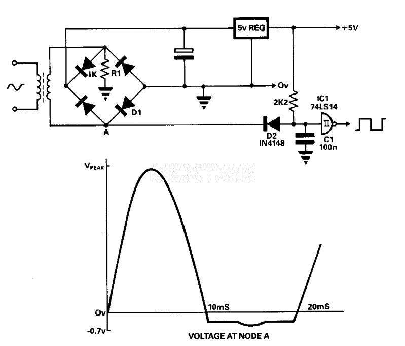
A line frequency square wave with a 1:1 duty cycle can be generated using only three components and a buffer from the power supply. During the alternate half-cycle, point A is clamped to approximately -0.7 V by diode D1...
The volt-ampere characteristics of a tunnel diode exhibit an S-shaped curve. The peak current point, referred to as point P, represents the maximum current, while the valley point, denoted as point V, indicates the minimum current. Key parameters of...
This simple circuit is sure to have the police beating a path to your door - however, it has the added advantage of alerting you to their presence even before their footsteps fall on the doormat. The described circuit functions...
This compact circuit consists of a single three-terminal integrated circuit (IC) UM66, which can be miniaturized enough to fit inside a greeting card, powered by a single 3V flat button cell. The circuit's simplicity is evident; the UM66 is...

This circuit diagram of a digital clock utilizes six common anode seven-segment displays to indicate the time. It does not require microcontrollers or PICs for operation. The circuit operates using the MM5314 integrated circuit, functioning at either 50 Hz...