
Square wave generator using uA 741

The square wave generator utilizing the uA741 operational amplifier (op-amp) is a fundamental circuit widely employed in various applications, including signal processing, waveform generation, and timing applications. The uA741 is a versatile op-amp that can be configured to produce a square wave output by employing a feedback mechanism and appropriate timing components.
In this circuit, the uA741 is configured in an astable multivibrator mode, which allows it to oscillate continuously without requiring any external triggering signal. The primary components involved in the circuit include the uA741 op-amp, resistors, and capacitors. The resistors set the charge and discharge times of the capacitor, thereby determining the frequency of the output square wave.
The circuit operates as follows: when powered on, the capacitor begins to charge through the resistors, causing the voltage across the capacitor to rise. Once the voltage reaches a certain threshold, the output of the uA741 switches states, transitioning from low to high. This change in output causes the capacitor to discharge through the resistors, lowering the voltage. When the voltage drops below a specific level, the output switches back, and the cycle repeats, generating a continuous square wave output.
The frequency of the generated square wave can be calculated using the formula:
\[ f = \frac{1.44}{(R1 + 2R2)C} \]
where \( R1 \) and \( R2 \) are the resistances in ohms, and \( C \) is the capacitance in farads. By adjusting the values of these components, the frequency of the square wave can be tailored to suit specific requirements.
In summary, the square wave generator circuit using the uA741 op-amp is an efficient and effective method for generating square wave signals. Its simplicity and ease of implementation make it a popular choice for various electronic applications.Square wave generator using uA741. Circuit diagram, theory and working principle.. 🔗 External reference
Related Circuits
This tiny circuit comprising of a single 3 terminal IC UM66 can be built small enough to be placed inside a greeting card and operated off a single 3V flat button cell. There is not much to the circuit....
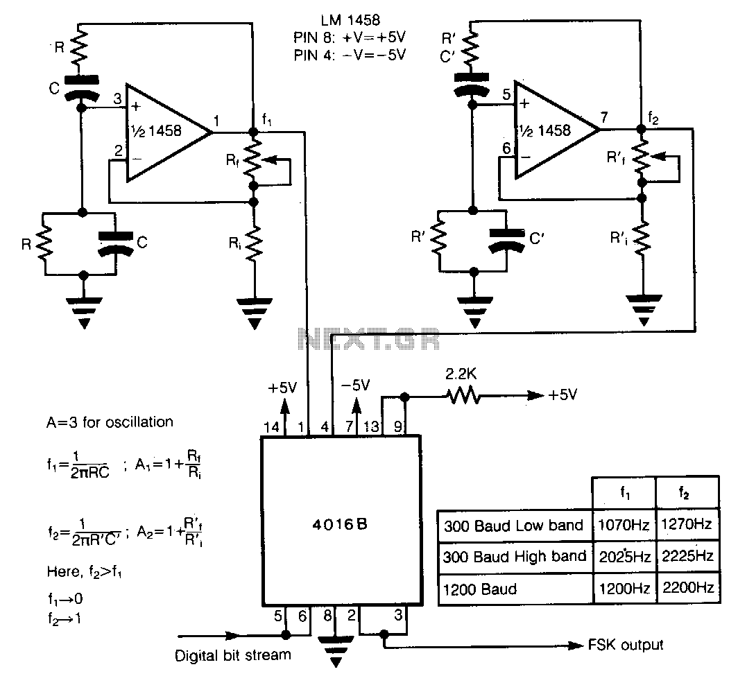
In Frequency Shift Keying (FSK), two distinct frequencies are utilized to represent the binary digits 0 and 1. The core of the circuit comprises two Wien-bridge oscillators constructed with a dual operational amplifier LM1458, each generating one of the...
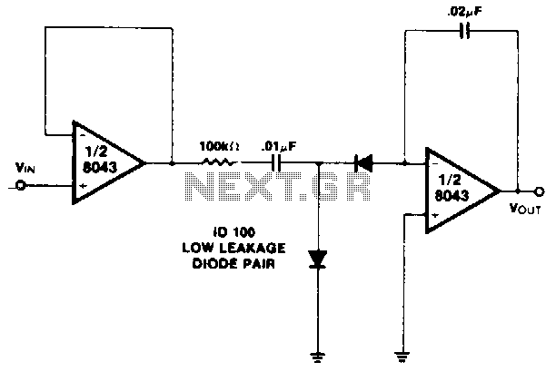
This circuit is a high-input impedance version of the diode pump or staircase generator. Charge transfer occurs at the negative-going edge of the input signal. The most common application for staircase generators is in low-cost counters. By resetting the...
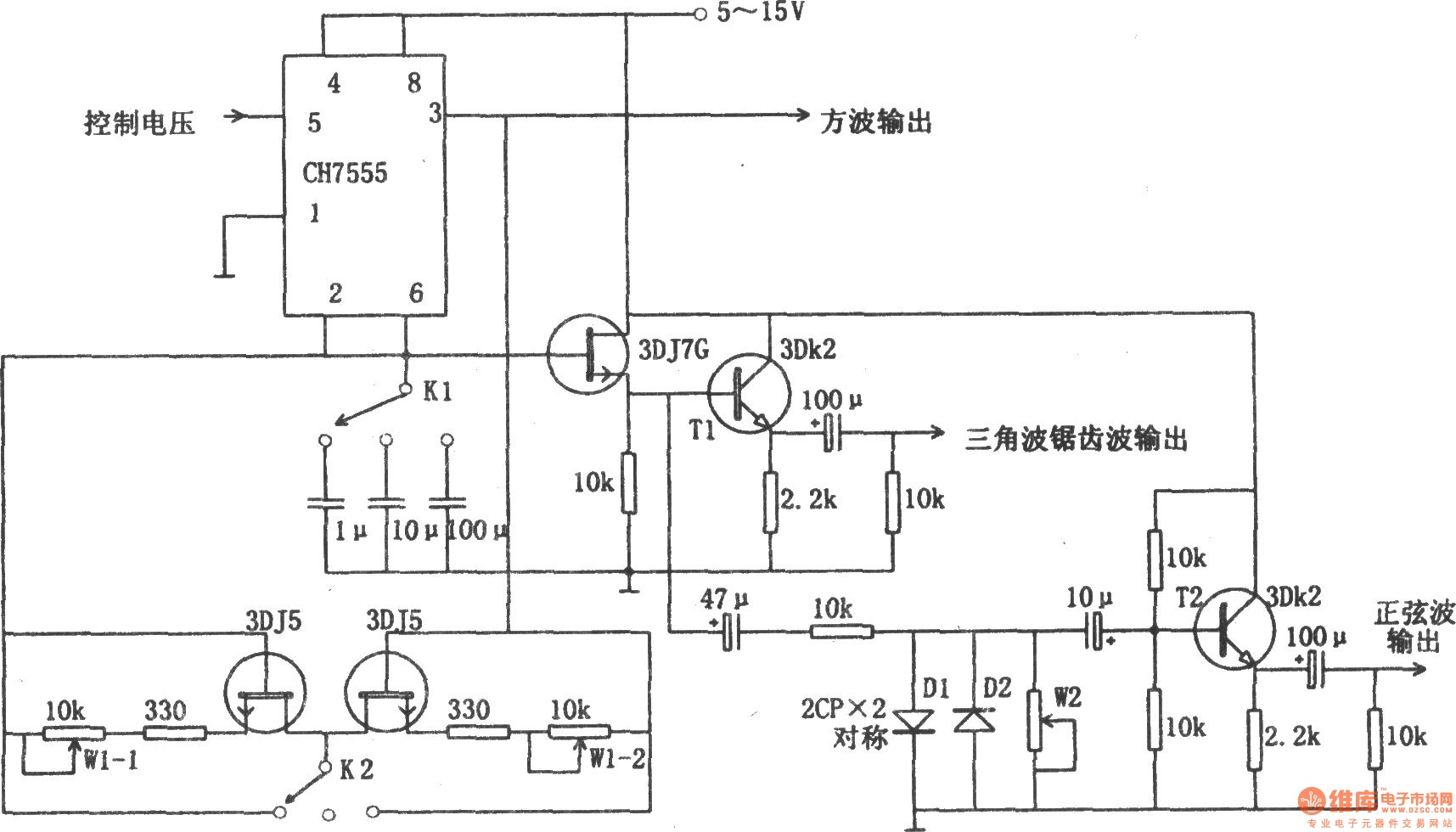
The chart illustrates a function generator circuit utilizing a 555 timer. This circuit includes a CH7555 timer along with several transistors and RC components. It is capable of generating triangle waves, square waves, sine waves, sawtooth waves, and square...
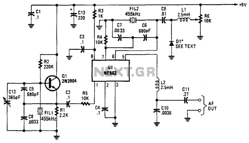
Q1 is a fixed oscillator operating at 455 kHz. U1 is a mixer with its own internal oscillator running at 45.5 kHz. FIL1 and FIL2 are Murata CSB455E filters or equivalent. D1 is a varactor diode (an IN4002 used...

This circuit design generates a stable 1 kHz sine wave using an inverted Wien bridge configuration with components C1-R3 and C2-R4. It offers a variable output, low distortion, and low output impedance to ensure good overload capability. The circuit...